A Boundary Signal Event object represents alternate workflow routing when that object receives a specific broadcasting Signal designed in Signal Manager. The Boundary Signal Event may associate with any of the following objects and connectors:
Form Task object
Script Task object
Manual Task object
Sub Process object
Actions By Email connector
Data Connector connector
DocuSign connector
IDP connector
PDF Generator connector
Send Email connector
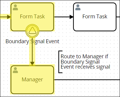
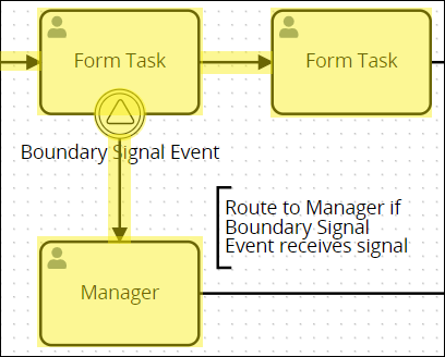
The Boundary Signal Event object associates with an object or connector by attaching to it to that object or connector. Below a Boundary Signal Event object associates with a Form Task object.

Boundary Signal Event object associates with a Form Task object
During an in-progress Request, if the object/connector to which the Boundary Signal Event associates has triggered but is not yet complete and the Boundary Signal Event object receives the broadcasting Signal for which it listens, then workflow routes through the Boundary Signal Event object. The object that broadcasts the Signal does not need to be in the same Process model as the Boundary Signal Event object to receive the broadcast Signal. If the broadcasting Signal is in a different Pool object within the same Process model, the Boundary Signal Event also triggers.
The Boundary Signal Event object receives any Request data in the broadcasting Signal's payload. Request data in the Signal's payload may be referenced when routing its Request.
If the object/connector to which the Boundary Signal Event object associates has not triggered when the Signal broadcasts, then the Boundary Signal Event object does not trigger.
Use an outgoing Sequence Flow object to indicate workflow routing from the Boundary Signal Event object if it triggers.
Use a Boundary Signal Event object to design business solutions when alternate workflow must occur in multiple Requests, even if those Requests derive from separate Processes. Consider these examples:
Escalate multiple Requests simultaneously to higher management: Use an Intermediate Signal Throw Event object to broadcast a specific signal to indicate that higher management needs to participate in multiple separate Requests simultaneously: when all Boundary Signal Event objects receive the specific Signal, workflow routes to alternate Task assignees to escalate a problem in each separate Request.
Broadcast a Signal when a separate Request completes: When a separate Request completes, a Signal End Event object broadcasts a specific Signal that indicates that Request's completion. All Boundary Signal Event objects from all in-progress Requests trigger simultaneously to route through alternate workflow. This design may be a business solution to indicate work on multiple Requests may not be necessary and workflow may route to end each of those Requests simultaneously.
Broadcast a Signal from a child sub-process: If during a Request for a child Sub Process broadcasts a Signal from an Intermediate Signal Throw Event or Signal End Event object, all Boundary Signal Event objects from all in-progress Requests trigger simultaneously to route through alternate workflow.
An object or connector associated with a Boundary Signal Event object may also associate with the following objects in the same object/connector:
Boundary Timer Event object
Boundary Error Event object
Boundary Conditional Event object
A Sub Process object associated with a Boundary Signal Event may also associate with a Boundary Message Event object.
Configure whether a Boundary Signal Event object interrupts the best-case scenario workflow:
Interrupting workflow: When workflow routes through the Boundary Signal Event object, workflow is interrupted and does not route through the best-case scenario. As highlighted in the example below, workflow routes through the Boundary Signal Event object if the Boundary Signal Event object receives the specific broadcasting Signal for which it is listening.
Non-interrupting workflow: Workflow routes both through the Boundary Signal Event object and the best-case scenario, thereby creating parallel workflow in that Request. As highlighted in the example below, workflow routes through the Boundary Signal Event object while the Form Task object is in progress; however, workflow also routes through the best-case scenario when the Form Task object completes.

Processes that use Boundary Signal Event objects can be complex. Therefore, use it to test workflow variations while designing such Processes.
Add a Boundary Signal Event to the Process Model
Permissions
Your user account or group membership must have the following permissions to configure a Boundary Signal Event object in the Process model unless your user account has the Make this user a Super Admin setting selected:
Processes: Edit Processes
Processes: View Processes
See the Process permissions or ask your Administrator for assistance.
Follow these steps to add a Boundary Signal Event object to the Process model:
View your Processes. The Processes page displays.
Create a new Process or click the Open Modeler icon
 to edit the selected Process model. Process Modeler displays.
Add one of the following Process model or connectors to your Process model in which to associate with the Boundary Signal Event object:
Actions By Email connector
Data Connector connector
DocuSign connector
IDP connector
PDF Generator connector
Send Email connector
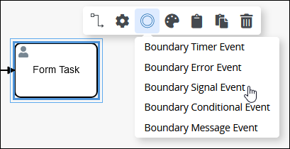
From the Boundary Events drop-down menu, select the Boundary Signal Event option.
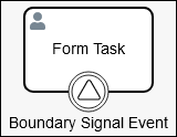
The Boundary Signal Event object displays on the top of its associating object/connector.
Settings
The Boundary Signal Event object has the following panels that contain settings:
Configuration panel
Documentation panel
Advanced panel
Configuration Panel Settings
The Boundary Signal Event object has the following settings in the Properties panel:
Edit the Object Name
An object name is a human-readable reference for a Process object. Process Modeler automatically assigns the name of a Process object with its object type. However, an object's name can be changed.
Follow these steps to edit the name for a Boundary Signal Event object:
Select the Boundary Signal Event object from the Process model in which to edit its name.
Ensure that the Configuration panel displays. If not, show it. The Name setting displays. This is a required setting.
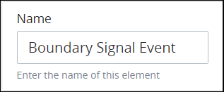
In the Name setting, edit the selected object's name and then press Enter.
Interrupt the Best-Case Scenario Workflow
Indicate whether the Boundary Signal Event object interrupts the best-case scenario workflow:
Interrupting workflow: When workflow routes through the Boundary Signal Event object, workflow is interrupted and does not route through the best-case scenario. As highlighted in the example below, workflow routes through the Boundary Signal Event object if the Boundary Signal Event object receives the specific broadcasting Signal for which it is listening if the Manual Task object is not complete when receiving that Signal.

Non-interrupting workflow: Workflow routes both through the Boundary Signal Event object and the best-case scenario, thereby creating parallel workflow in that Request. As highlighted in the example below, workflow routes through the Boundary Signal Event object if the Manual Task object is not yet complete; however, workflow also routes through the best-case scenario when that object completes.
Follow these steps to indicate if this Boundary Signal Event object interrupts the best-case scenario workflow when it triggers:
Select the Boundary Signal Event object from the Process model in which to indicate if it interrupts the best-case scenario workflow.
Ensure that the Configuration panel displays. If not, show it. Panels to configure this object display.
Expand the Configuration panel if it is not presently expanded, and then locate the Interrupting setting.
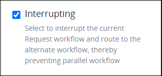
From the Interrupting checkbox, indicate whether this Boundary Signal Event object interrupts the best-case scenario workflow when it triggers. When the Interrupting checkbox is selected, which is the default setting, this object interrupts the best-case scenario workflow.
Select the Signal to Trigger the Object
A Boundary Signal Event object represents alternate workflow routing when that object receives a specific broadcasting Signal. The object that broadcasts the Signal does not need to be in the same Process model as the Boundary Signal Event object to receive the broadcasting Signal. Use a Boundary Signal Event object to design business solutions when alternate workflow must occur simultaneously across multiple Process Requests when a separate object in a separate Request broadcasts a Signal for which any or all Boundary Signal Event objects is listening. Select the Signal that triggers this object.
Follow these steps to select the Signal that triggers the Boundary Signal Event object:
Select the Boundary Signal Event object from the Process model in which to select the Signal that triggers it.
Ensure that the Configuration panel displays. If not, show it. Panels to configure this object display.
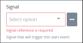
Expand the Configuration panel if it is not presently expanded, and then locate the Signal setting.
Do one of the following:
The Signal to trigger this object exists:
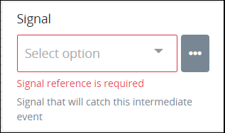
From the Signal drop-down menu, select the Signal that triggers this object. This setting is required.
The Signal to trigger this object does not exist:
Click the menu icon
 beside the Signal drop-down menu. The +Signal button displays.
Click the +Signal button. The ID and Name settings display to configure the new Signal's ID and name, respectively.
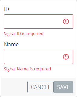
In the ID setting, enter the unique ID of this Signal. The Signal ID may only contain non-special characters and without spaces. This Signal ID must be unique from all other signal IDs. If the entered Signal ID already exists, the following text displays below the setting: Signal ID is duplicated. Note that the Signal ID cannot be edited after the Signal is created. Consider the following when entering the Signal ID value:
Signal IDs must be unique and accept alphanumeric characters only.
A Signal that corresponds with a User Signal must have the Signal ID value that corresponds with that User Signal's event. See What is a User Signal?. Ensure that the User Signal is enabled for use.
This is a required setting.
In the Name setting, enter the unique alphanumeric name of this Signal. This Signal name must be unique from all other Signal names. This Signal name displays when selecting a Signal from other objects that can broadcast or listen for a Signal. If the entered Signal name already exists, the following text displays below the setting: Signal Name is duplicated. This is a required setting.
Click Save. The Signal is created.
From the Signal drop-down menu, select the new Signal that triggers this object. This setting is required.
Save your Process model. The new Signal is added to Signal Manager.
Edit the Name of a Signal
Editing the name of a Signal changes that signal's name. This Signal name displays when selecting a Signal from other objects that can broadcast or listen for a Signal.
Follow these steps to edit the name of a Signal:
Select any object from the Process model that broadcasts or listens for a Signal.
Ensure that the Configuration panel displays. If not, show it. Panels to configure this object display.
Expand the Configuration panel if it is not presently expanded, and then locate the Signal setting. The Signal setting may have a selection unlike the image below indicates.
Click the menu icon
beside the Signal drop-down menu. All Signals configured in your ProcessMaker Platform instance display below the +Signal button. The Signal ID displays in a gray border; the Signal name displays to the right of the Signal ID. 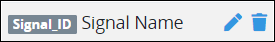
Click the Edit icon
 that displays beside each Signal to edit that signal. The Name setting displays the name of that Signal.
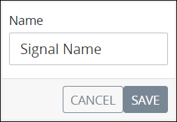
In the Name setting, edit the name of the Signal as necessary.
Click Save.
Save your Process model. The name of the Signal also changes in Signal Manager.
Delete a Signal from the Instance
A Signal cannot be delete if any other Signal subscribes to it. When attempting to delete a Signal with any subscribing object, a message displays with which object(s) subscribes to that Signal.
Carefully consider whether to delete a Signal. Deleting a Signal makes that Signal unavailable when configuring all objects that broadcast or listen to Signals throughout your ProcessMaker Platform instance.
Deleting a Signal cannot be undone.
Follow these steps to delete a Signal:
Select any object from the Process model that broadcasts or listens for a Signal.
Ensure that the Configuration panel displays. If not, show it. Panels to configure this object display.
Expand the Configuration panel if it is not presently expanded, and then locate the Signal setting. The Signal setting may have a selection unlike the image below indicates.
Click the menu icon
beside the Signal drop-down menu. All Signals configured in your ProcessMaker Platform instance display below the +Signal button. The Signal ID displays in a gray border; the Signal name displays to the right of the Signal ID. Click the Delete icon
 that displays beside each Signal to delete that Signal. A message displays to confirm deletion of this Signal.
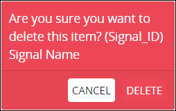
If the Signal is subscribed to by another object anywhere in your ProcessMaker Platform instance, that Signal cannot be deleted. A message displays by which object(s) subscribes to this Signal.
Click Delete.
Save your Process model. The Signal is also deleted from Signal Manager.
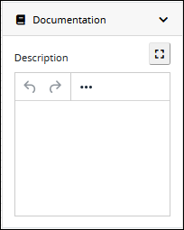
Documentation Panel Settings
Describe the object's purpose and how it functions in the Process. This description does not affect Requests for the Process, but may be useful for Process model maintenance such as how the object is configured. Edit information by using the What-You-See-Is-What-You-Get (WYSIWYG) rich text editor.
A Process's entered documentation displays by selecting the View Documentation icon for that Process.
Edit the Object's Description Displayed in Process Documentation
Follow these steps to edit the description for an object:
Select the object from the Process model in which to edit its description.
Ensure that the Configuration panel displays. If not, show it. Panels to configure this object display.
Expand the Documentation panel if it is not presently expanded. The Description setting displays.
In the Description setting, edit the information to display when viewing documentation for this object and then press Enter. Alternatively, use the What-You-See-Is-What-You-Get (WYSIWYG) rich text editor to stylize your text by clicking the More icon
 .
. 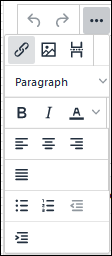
Follow these guidelines to use the WYSIWYG rich text editor to stylize your text:
Undo changes: Click on the
 icon to undo the last action.
Redo changes: Click on the
 icon to redo the last undone action.
Insert/Edit Link: Click on the
 icon to convert the selected text into a hyperlink. Follow these steps to create a hyperlink:
 Select the required text from the Rich Text control.
Click on the
icon. The Insert/Edit Link screen displays.
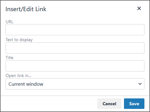
In the URL setting, enter the destination URL.
In the Text to display setting, edit or enter the text displayed in the Rich Text control.
In the Title setting, enter the text to display when a user hovers over the displayed text.
From Open link in… drop-down menu, select one of these options:
New window: Select this option to open the destination page in a new browser window.
Current window: Select this option to open the destination page in the current browser window.
Insert/Edit Image: Click on the Insert/Edit Image icon
 to insert an image. Follow these guidelines:
 Click on the Insert/Edit Image icon
. The Insert/Edit Image screen displays:
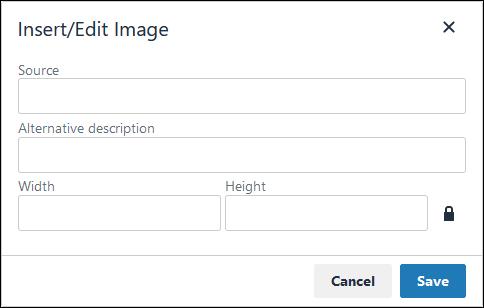
In the Source setting, enter a URL for the image.
In the Alternative Description setting, enter the text to display if the source URL of the image is not accessible.
In the Width setting, enter the maximum width for the image.
In the Height setting, enter the maximum height for the image.
Toggle the Constrain Proportions icon
 to maintain the width-height ratio of the image to its original proportion.
 Click Save.
Insert Page Break for PDF: Click on the Insert Page Break for PDF icon
 to insert a page break when a PDF document is created for this documentation if your browser supports this feature.
 Format text: Follow these guidelines to format text:
Headings: From the Paragraph/Formats menu, select Headings and then select a heading size.
Bold: Do one of the following:
From the editor toolbar, select the
 icon.
icon.From the Paragraph/Formats menu, select Inline and then Bold.
Italics: Do one of the following:
From the editor toolbar, select the
 icon.
icon.From the Paragraph/Formats menu, select Inline and then Italic.
Underline: From the Paragraph/Formats menu, select Inline and then Underline.
Strikethrough: From the Paragraph/Formats menu, select Inline and then Strikethrough.
Superscript: From the Paragraph/ Formats menu, select Inline and then Superscript.
Subscript: From the Paragraph/Formats menu, select Inline and then Subscript.
Code: From the Paragraph/Formats menu, select Inline and then Code.
Paragraph: From the Paragraph/Formats menu, select Blocks and then Paragraph.
Blockquote: From the Paragraph/Formats menu, select Blocks and then Blockquote.
Division: From the Paragraph/Formats menu, select Blocks and then Div.
Preformatted: From the Paragraph/Formats menu, select Blocks and then Pre.
Change text color: Use the Text Color drop-down to change text color. Click on the
 icon. The color palette displays. Do one of the following:
Select one of the color swatches from the color palette. The selected text changes to that color.
Click the
 icon to select a custom color from the Color Picker.
Click the
 icon to reset the text to its default color.
Align text: Follow these guidelines to align text:
Left align: Do one of the following:
From the editor toolbar, use the
 icon to left-align text.
From the Paragraph/Formats menu, select Align and then Left.
Center align: Do one of the following:
From the editor toolbar, use the
 icon to center-align text.
From the Paragraph/Formats menu, select Align and then Center.
Right align: Do one of the following:
From the editor toolbar, use the
 icon to right-align text.
From the Paragraph/Formats menu, select Align and then Right.
Justify: Do one of the following:
From the editor toolbar, use the
 icon to justify text.
 From the Paragraph/Formats menu, select Align and then Justify.
Insert a bullet list: Use the
 icon to format text as a bulleted list.
Insert a numbered list: Use the
 icon to format text as a numbered list.
Indent text: Click on the
 icon to increase text indenting.
Outdent text: Click on the
 icon to decrease text indenting.
Advanced Panel Settings
Edit the Node's Identifier Value
Process Modeler automatically assigns a unique value to each Process node added to a Process model. However, a node's identifier value can be changed if it is unique to all other nodes in the Process model, including the Process model's identifier value.
All identifier values for all nodes in the Process model must be unique.
Follow these steps to edit the identifier value for a Boundary Signal Event object:
Select the Boundary Signal Event object from the Process model in which to edit its identifier value.
Ensure that the Configuration panel displays. If not, show it. Panels to configure this object display.
Expand the Advanced panel if it is not presently expanded. The Node Identifier setting displays. This is a required setting.
In the Node Identifier setting, edit the Boundary Signal Event object's identifier to a unique value from all nodes in the Process model and then press Enter.