A Sub Process object calls a Sub Process that can be re-used by other Processes. The Sub Process that the Sub Process object calls is referred to as the "child" Sub Process and must be an external Process from the calling Process it (referred to as the "parent" Process).
The child Sub Process that the Sub Process object calls from the parent Process's Request must be in the same ProcessMaker Platform instance and not archived.
The child Sub Process has its own Request. The Request for the parent Process waits until the child Sub Process's Request completes before its workflow continues. When the child Sub Process's Request completes, the parent Process's Request continues from the Sub Process object.
To prevent routing for the parent Process's Request from waiting until the child Sub Process's Request completes, use a Parallel Gateway object preceding the Sub Process object. Use a parallel outgoing Sequence Flow object from the Parallel Gateway object to continue routing the parent Process while the Sub Process object waits for the child Sub Process's Request to complete.
Add a Sub Process to the Process Model
Permissions
Your user account or group membership must have the following permissions to configure a Sub Process object in the Process model unless your user account has the Make this user a Super Admin setting selected:
Processes: Edit Processes
Processes: View Processes
See the Process permissions or ask your Administrator for assistance.
Add a Sub Process object from one of the following locations in Process Modeler:
Object Panel: Located to the left of the Process Modeler, the Object Panel contains various process modeling objects.
Object Bar: Located at the bottom of the Process Modeler, the Object Bar contains pinned Process modeling objects for quick access.
Follow these steps to add a Sub Process from the Object panel to the Process model:
Ensure that the Object panel is visible. If not, click the Add icon
 from the Object bar at the bottom.
Click the Task object
 from the Object panel to select it.
Click the location in the Process model to place this object. Follow these guidelines when placing this object:
If your process has a Pool object, the object cannot be placed outside of the Pool object.
To place this object between two existing objects, follow these instructions.
Click the Objects drop-down menu, and then select the Script Task option.
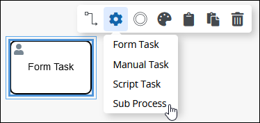
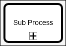
The Sub Process object displays.
Follow these steps to add a Sub Process object from the Object bar to the Process model:
Ensure that the object is pinned to the Object bar. If not, see instructions to pin it.
In the Object bar at the bottom center, click the object's icon.
Click the location in the Process model to place this object. Follow these guidelines when placing this object:
If your process has a Pool object, the object cannot be placed outside of the Pool.
To place this object between two existing objects, follow these instructions.
Click the Objects drop-down menu, and then select the Script Task option.
The Sub Process object displays.
Add boundary events
- Boundary Timer Event element
- Boundary Error Event element
- Boundary Signal Event element
- Boundary Conditional Event element
- Boundary Message Event element
Replace a Sub Process Object with a Task Type Object
After a Sub Process object is added to a Process model, you may replace it with a Task type object:
Form Task object
Manual Task object
Script Task object
The selected Sub Process object is replaced by the default settings and color of the replacing object.
Follow these steps to replace a Sub Process object with a Task type object:
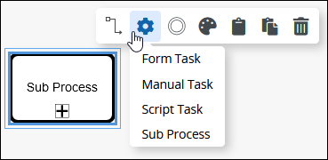
Select the Sub Process object to change to another object. Available options display above the selected object.
Click the Objects icon. The Objects drop-down menu displays the Task type objects and the Sub Process object.
Select the object to replace the Sub Process object. The Change Type screen displays to confirm replacing the currently selected object.
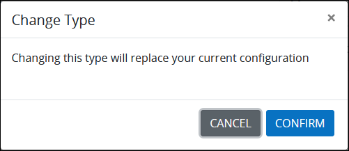
Click Confirm. The new object replaces the Sub Process object with its default settings and color.
Settings
The Sub Process object has the following panels that contain settings:
Properties panel
Loop Characteristics panel
Documentation panel
Assignment Rules panel
Advanced panel
Properties Panel Settings
The Sub Process object has the following settings in the Properties panel:
Edit the Object Name
An object name is a human-readable reference for a Process object. Process Modeler automatically assigns the name of a Process object with its object type. However, an object's name can be changed.
Follow these steps to edit the name for a Sub Process object:
Select the Sub Process object from the Process model in which to edit its name.
Ensure that the Configuration panel displays. If not, show it. The Name setting displays. This is a required setting.
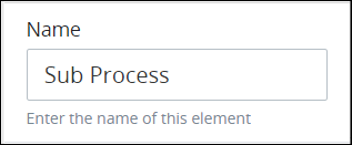
In the Name setting, edit the selected object's name and then press Enter.
Select the "Child" Sub Process This Object Calls
The Sub Process object calls a Sub Process when it triggers. The Sub Process is referred to as a "child" Process, while the calling Process is referred to as the "parent" Process. The child Sub Process must in the same ProcessMaker instance as the parent Process and not archived.
The child Sub Process has its own Request. The Request for the parent Process waits until the child Sub Process's Request completes before its workflow continues. When the child Sub Process's Request completes, the parent Process's Request continues from the Sub Process object.
The child Process must have at least one Start Event object from which to start its Request. Other Start-type BPMN objects result in an invalid parent Process error when this Sub Process object calls the child Process to start its Request.
As a best practice, verify that the child Process contains a Start Event object prior to completing design for the Process using this Sub Process object.
To prevent routing for the parent Process's Request from waiting until the child Sub Process's Request completes, use a Parallel Gateway object preceding the Sub Process object. Use a parallel outgoing Sequence Flow object from the Parallel Gateway object to continue routing the parent Process while the Sub Process object waits for the child Sub Process's Request to complete.
Follow these steps to select the child Sub Process the Sub Process object calls when it triggers:
Select the Sub Process object from the Process model in which to select the child Sub Process that object calls.
Ensure that the Configuration panel displays. If not, show it. Panels to configure this object display.
Expand the Configuration panel if it is not presently expanded, and then locate the Process setting.
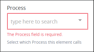
From the Process drop-down menu, select which child Sub Process the Sub Process object calls when it triggers. This is a required setting. After selecting a Process from the Process drop-down menu, the Start Event setting displays. A Start Event object from the selected Process displays in the Start Event drop-down menu.
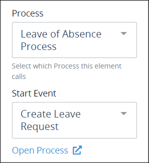
From the Start Event drop-down menu, select another Start Event object from the child Process that this Sub Process object calls to start a Request if the default Start Event object is not to be called. Optionally click the Open Process option below the Start Event drop-down menu to review the selected Process model in a new Web browser window.
Add a Placeholder for the Slideshow Mode
The Slideshow Mode makes it easy for process designers to share the design of a process with all stakeholders, regardless of whether they have access to the ProcessMaker Platform. For more information on how to create slideshows for a process, see Slideshow Mode.
Follow these steps to add a placeholder image for the Slideshow Mode:
Select the Form Task object from the Process model.
Click the
.png) icon to view the Configuration panel.
icon to view the Configuration panel.From the Placeholder for Slideshow section, click on the +Drag or click here button to upload an image.
.png "image(295).png")
A preview of the image will display, and the configuration will be auto-saved.
.png "image(296).png")
The uploaded image will be shown for this task the next time the slideshow is viewed.
Notes:
Size of a placeholder image for slideshows must less than 2 MB.
Image files with PNG, JPG, JPEG, and GIF extensions are supported.
Loop Characteristics Panel Settings
Use the Loop Activity panel settings to specify how to perform multiple instances of this object. The following loop modes are available:
No Loop Mode
Select the No Loop Mode option to perform this object's Task only once.
Follow these steps to specify characteristics to perform multiple instances of the Task:
Select the Task from the Process model. Panels to configure this object display.
Expand the Loop Activity panel. By default, the Loop Mode setting is set to No Loop Mode and the function is performed only once.
.png "image(291).png")
Loop
Select the Loop option to sequentially repeat this Task's function multiple times until an exit condition is True. This is useful when a function should be performed multiple times with the same set of data, such as, processing a credit card payment. This loop mode has the following characteristics:
The Task's function is repeated until the exit condition is
Trueor the maximum iterations limit is reached.At any given time, only one instance of the Task is active. The subsequent instance does not begin until the current instance completes.
The same exit condition evaluates at the end of each instance; however, value(s) of the Request variable(s) used in the exit condition can change during an instance resulting in the exit condition to eventually evaluate as
True.If any one instance of that function does not complete, workflow pauses.
All active instances are terminated if an interrupting boundary-type event object triggers.
 An object configured in this mode shows the Loop icon in Process Modeler.
Follow these steps to specify characteristics to perform multiple instances of the Task:
Select the Task from the Process model in which to specify multiple instance characteristics. Panels to configure this object display.
Expand the Loop Activity panel to display the Loop Mode Setting.
From the Loop Mode setting, select the Loop option. The settings for this loop mode display:
.png "image(292).png")
In the Maximum Iterations setting, enter an integer value representing the maximum number of times this Task should be performed.
In the Exit Condition setting, enter a condition in FEEL syntax. When this condition is True the loop activity is halted.
Multi-instance (Sequential)
Select the Multi-instance (Parallel) option to perform this Task's Task multiple times in parallel a fixed number of times. This is useful when performing any action in bulk, such as sending an email to several people. This loop mode has the following characteristics:
Instances of the Task are governed by the size of an array-type Request variable where a new instance is created for each item in this variable. For example, an array with 10 items will create 10 parallel instances of this function that each contains data from its respective array index.
All instances begin simultaneously when this Task triggers; however, they perform their function independently of each other.
The function as a whole completes when all instances are complete.
The output from each instance can either be saved in the source Request variable or a new array-type Request variable.
All active instances terminate if an interrupting boundary-type event object triggers.
A Task configured in this mode shows the Multi-instance (Parallel) icon
 in Process Modeler.
Follow these steps to specify characteristics to perform multiple instances of the Task:
Select the Task from the Process model in which to specify multiple instance characteristics. Panels to configure this object display.
Expand the Loop Activity panel to display the Loop Mode Setting.
From the Loop Mode setting, select the Multi-instance (Parallel) option. The settings for this loop mode display:
.png "image(293).png")
In the Request Variable Array setting, enter the name of an array-type Request variable. The size of this array will determine how many times this loop iterates.
In the Output Data Variable setting, enter the name of an array-type Request variable in which to store the results of all instances. Each instance of the loop saves to a separate JSON object within the array of the specified Request variable. If the Output Data Variable setting is not configured, then the output data replaces the source data in the Request Variable Array.
Multi-instance(Sequential)
Select the Multi-instance (Sequential) option to perform this Task's function multiple times sequentially a fixed number of times or until an exit condition is True. This is useful when sequentially repeating a function multiple times but with a different set of data each time. This loop mode has the following characteristics:
Instances of the function are governed by the size an array-type Request variable where a new instance is created for each item in this variable. For example, an array with 10 items will create 10 parallel instances of this function that each contains data from its respect array index.
At any given time, only one instance of the function is active. The subsequent instance does not begin until the current instance completes.
At the end of each instance an exit condition evaluates and the loop activity halts if the exit condition is
True.The function as a whole completes when all instances are complete.
The output from each instance can either be saved in the source Request variable or a new array-type Request variable.
All active instances terminate if an interrupting boundary-type event object triggers.
A Task configured in this mode shows the Multi-instance (Sequential) icon
.png) in Process Modeler.
in Process Modeler.
Follow these steps to specify characteristics to perform multiple instances of the Task:
Select the Task from the Process model in which to specify multiple instance characteristics. Panels to configure this object display.
Expand the Loop Activity panel to display the Loop Mode Setting.
From the Loop Mode setting, select the Multi-instance (Sequential) option. The settings for this loop mode display:
.png "image(294).png")
In the Request Variable Array setting, enter the name of an array-type Request variable. The size of this array will determine how many times this loop iterates.
In the Exit Condition setting, enter a condition in FEEL syntax. When this condition is True the loop activity is halted.
In the Output Data Variable setting, enter the name of an array-type Request variable in which to store the results of all instances. Each instance of the loop saves to a separate JSON object within the array of the specified Request variable. If the Output Data Variable setting is not configured, then the output data replaces the source data in the Request Variable Array.
Documentation Panel Settings
Describe the object's purpose and how it functions in the Process. This description does not affect Requests for the Process, but may be useful for Process model maintenance such as how the object is configured. Edit information by using the What-You-See-Is-What-You-Get (WYSIWYG) rich text editor.
A Process's entered documentation displays by selecting the View Documentation icon for that Process.
Edit the Object's Description Displayed in Process Documentation
Follow these steps to edit the description for an object:
Select the object from the Process model in which to edit its description.
Ensure that the Configuration panel displays. If not, show it. Panels to configure this object display.
Expand the Documentation panel if it is not presently expanded. The Description setting displays.
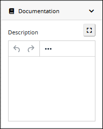
In the Description setting, edit the information to display when viewing documentation for this object and then press Enter. Alternatively, use the What-You-See-Is-What-You-Get (WYSIWYG) rich text editor to stylize your text by clicking the More icon
 .
.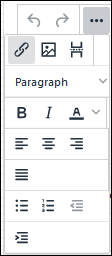
Follow these guidelines to use the WYSIWYG rich text editor to stylize your text:
Undo changes: Click on the
 icon to undo the last action.
Redo changes: Click on the
 icon to redo the last undone action.
Insert/Edit Link: Click on the
 icon to convert the selected text into a hyperlink. Follow these steps to create a hyperlink:
 Select the required text from the Rich Text control.
Click on the
icon. The Insert/Edit Link screen displays. 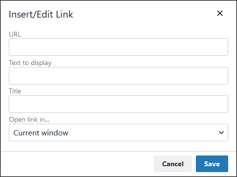
In the URL setting, enter the destination URL.
In the Text to display setting, edit or enter the text displayed in the Rich Text control.
In the Title setting, enter the text to display when a user hovers over the displayed text.
From Open link in… drop-down menu, select one of these options:
New window: Select this option to open the destination page in a new browser window.
Current window: Select this option to open the destination page in the current browser window.
Insert/Edit Image: Click on the Insert/Edit Image icon
 to insert an image. Follow these guidelines:
 Click on the Insert/Edit Image icon
. The Insert/Edit Image screen displays:
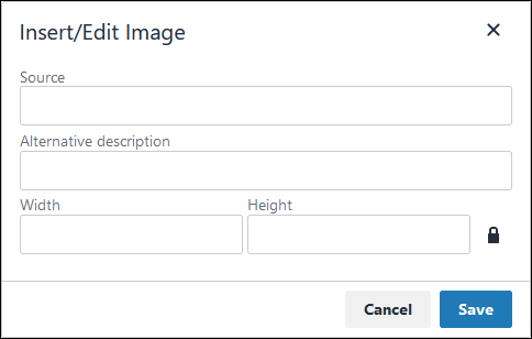
In the Source setting, enter a URL for the image.
In the Alternative Description setting, enter the text to display if the source URL of the image is not accessible.
In the Width setting, enter the maximum width for the image.
In the Height setting, enter the maximum height for the image.
Toggle the Constrain Proportions icon
 to maintain the width-height ratio of the image to its original proportion.
 Click Save.
Insert Page Break for PDF: Click on the Insert Page Break for PDF icon
 to insert a page break when a PDF document is created for this documentation if your browser supports this feature.
 Format text: Follow these guidelines to format text:
Headings: From the Paragraph/Formats menu, select Headings and then select a heading size.
Bold: Do one of the following:
From the editor toolbar, select the
 icon.
icon.From the Paragraph/Formats menu, select Inline and then Bold.
Italics: Do one of the following:
From the editor toolbar, select the
 icon.
icon.From the Paragraph/Formats menu, select Inline and then Italic.
Underline: From the Paragraph/Formats menu, select Inline and then Underline.
Strikethrough: From the Paragraph/Formats menu, select Inline and then Strikethrough.
Superscript: From the Paragraph/ Formats menu, select Inline and then Superscript.
Subscript: From the Paragraph/Formats menu, select Inline and then Subscript.
Code: From the Paragraph/Formats menu, select Inline and then Code.
Paragraph: From the Paragraph/Formats menu, select Blocks and then Paragraph.
Blockquote: From the Paragraph/Formats menu, select Blocks and then Blockquote.
Division: From the Paragraph/Formats menu, select Blocks and then Div.
Preformatted: From the Paragraph/Formats menu, select Blocks and then Pre.
Change text color: Use the Text Color drop-down to change text color. Click on the
 icon. The color palette displays. Do one of the following:
Select one of the color swatches from the color palette. The selected text changes to that color.
Click the
 icon to select a custom color from the Color Picker.
Click the
 icon to reset the text to its default color.
Align text: Follow these guidelines to align text:
Left align: Do one of the following:
From the editor toolbar, use the
 icon to left-align text.
From the Paragraph/Formats menu, select Align and then Left.
Center align: Do one of the following:
From the editor toolbar, use the
 icon to center-align text.
From the Paragraph/Formats menu, select Align and then Center.
Right align: Do one of the following:
From the editor toolbar, use the
 icon to right-align text.
From the Paragraph/Formats menu, select Align and then Right.
Justify: Do one of the following:
From the editor toolbar, use the
 icon to justify text.
 From the Paragraph/Formats menu, select Align and then Justify.
Insert a bullet list: Use the
 icon to format text as a bulleted list.
Insert a numbered list: Use the
 icon to format text as a numbered list.
Indent text: Click on the
 icon to increase text indenting.
Outdent text: Click on the
 icon to decrease text indenting.
Assignment Rules Panel Settings
Select who may start Requests for the "child" Sub Process selected from the Process setting:
Anonymous: Any person may start Requests for the child Sub Process. Ensure that the child Sub Process contains a Start Event object configured to allow anonymous Web Entry; otherwise, that Start Event object only allows authenticated users to start Requests for the child Sub Process.
Requester: Only the person who started that Request for the "parent" Process may start Requests for the child Sub Process. This user is known as the Request starter.
Users and/or groups: Selected users and/or all members of selected groups may start Requests for the child Sub Process.
Previous Task assignee: Only the previous Task assignee in that Request may start Requests for the child Sub Process.
By User ID: A user based on a Variable Name value as entered into a Screen during a previous Task in that Request may start Requests for the child Sub Process. For example, if a Line Input control in a Screen has the Variable Name value of
Name, to contain a user's name, then use that value to thereby select that user to start Sub child Process Requests.
Select Who May Start Requests for the "Child" Sub Process
Follow these steps to select who may start Requests for the child Sub Process:
Select the Sub Process object from the Process model in which to select who may start Requests for the child Sub Process.
Ensure that the Configuration panel displays. If not, show it. Panels to configure this object display.
Expand the Assignment Rules panel if it is not presently expanded. The Start Sub Process As setting displays.
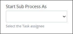
From the Start Sub Process As drop-down menu, select one of the following options:
Anonymous: Select Anonymous to allow any person to start Requests for the child Sub Process. Ensure that the child Process contains a Start Event object configured to allow anonymous Web Entry; otherwise, that Start Event object only allows authenticated users to start Requests of the child Sub Process.
Requester: Select Requester to only allow the Request starter to start Requests for the child Sub Process.
Users and/or Groups: Select Users/Groups to choose specific users and/or all members of specific groups may start Requests for the child Sub Process. When this option is selected, the Assigned Users/Groups drop-down menu displays below the Start Sub Process As drop-down menu.
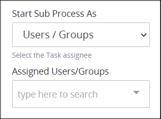
From the Assigned Users/Groups drop-down menu, select as all users and/or groups that may start Requests for the child Process. Multiple ProcessMaker users and/or groups may be added, one at a time, to this setting. You may click the Remove icon to remove a selection from the Assigned Users/Groups drop-down menu.
Previous Task Assignee: Select Previous Task Assignee to only allow the previous Task assignee in that Request to start Requests for the child Sub Process.
By User ID: Select By User ID to select a user based on a Variable Name value as entered into a Screen during a previous Task in that Request may start Requests for the child Sub Process.
For example, if a Line Input control in a Screen has the Variable Name value of
Name, to contain a user's name, then use that value to thereby select that user to start child Sub Process Requests. When this option is selected, the Variable Name of User ID Value setting displays.In the Variable Name of User ID Value setting, enter the Variable Name value from which to reference the user who may start child Sub Process Requests.
Advanced Panel Settings
Edit the Node's Identifier Value
Process Modeler automatically assigns a unique value to each Process node added to a Process model. However, a node's identifier value can be changed if it is unique to all other nodes in the Process model, including the Process model's identifier value.
All identifier values for all nodes in the Process model must be unique.
Follow these steps to edit the identifier value for a Sub Process object:
Select the Sub Process object from the Process model in which to edit its identifier value.
Ensure that the Configuration panel displays. If not, show it. Panels to configure this object display.
Expand the Advanced panel if it is not presently expanded. The Node Identifier setting displays. This is a required setting.
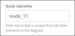
In the Node Identifier setting, edit the Sub Process object's identifier to a unique value from all nodes in the Process model and then press Enter.