Smart Extract
Smart Extract is a built-in capability in ProcessMaker that enables automated document data extraction within a process. It allows documents (such as PDFs and images) to be processed automatically to identify and extract structured data points, such as fields and values, based on a configured model. Smart Extract is intended to reduce manual data entry and accelerate workflows that involve document processing. It can be added to a process directly from the Process Modeler and configured with a specific extraction model and parameters to control how documents are analyzed and parsed.
Smart Extract automatically evaluates uploaded documents and applies defined extraction logic to identify relevant data. The results of the extraction are stored in Request variables and can be used in subsequent process steps, enabling automated decision-making and data-driven workflow progression without leaving the ProcessMaker Platform.
Human-in-the-Loop (HITL) Validation
Human-in-the-Loop (HITL) validation is an extension of Smart Extract that introduces a manual review step when automated extraction results do not meet predefined quality or validation criteria. Process Designers can define configurable rules that evaluate extraction confidence, completeness, or other conditions. When an extracted document fails to satisfy these rules, the process automatically routes the case to a human validation task rather than proceeding with potentially incorrect data .
Operators assigned to HITL review tasks can then validate and correct the extracted data using a secure Smart Extract interface embedded directly within ProcessMaker. This approach balances the efficiency of automation with human oversight, ensuring that critical data is accurate before the process continues. Once the manual review is complete, the process resumes automatically based on the review outcome, with any corrections applied to the extracted data.
Add an Smart Extract Connector to the Process Model
Permissions
Your user account or group membership must have the following permissions to configure an Smart Extract connector to the Process model unless your user account has the Make this user a Super Admin setting selected:
Processes: Edit Processes
Processes: View Processes
See the Process permissions or ask your Administrator for assistance.
Add an Smart Extract connector from one of the following locations in Process Modeler:
Object Panel: Located to the left of the Process Modeler canvas, the Object Panel contains various process model objects.
Object Bar: Located at the bottom of the Process Modeler canvas, the Object Bar contains pinned Process model objects for quick access.
Follow these steps to add an Smart Extract connector from the Object panel to the Process model:
Ensure that the Object panel is visible on the left. If not, click the Add icon
 from the Object bar at the bottom.
Click the Smart Extract object
 from the Object panel to select it.
Click the location in the Process model to place this connector. Follow these guidelines when placing this object:
If your process has a Pool object, the Smart Extract object cannot be placed outside of the Pool.
To place this object between two existing objects, follow these instructions.
Follow these steps to add an Smart Extract connector from the Object bar to the Process model:
Ensure that the Smart Extract object
 is pinned to the Object bar. If not, see instructions to pin it it.
In the Object bar at the bottom center, click the object's icon.
Click the location in the Process model to place this element. Follow these guidelines when placing this object:
If your process has a Pool object, the Smart Extract object cannot be placed outside of the Pool.
To place this object between two existing objects, follow these instructions.
Add boundary events
- Boundary Timer Event element
- Boundary Error Event element
- Boundary Signal Event element
- Boundary Conditional Event element
- Boundary Message Event element
Settings
The Smart Extract connector has the following panels that contain settings:
Configuration panel
Loop Activity panel
HITL Assignee panel
Advanced panel
Configuration Panel Settings
The Smart Extract connector has multiple settings in the Configuration panel.
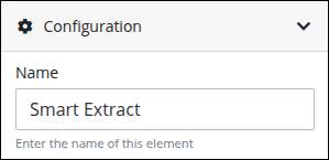
Edit the Connector Name
A connector name is a human-readable reference for a Process model control. Process Modeler automatically assigns the name of a Process model connector with its connector type. However, a connector's name can be changed.
Follow these steps to edit the name for an Smart Extract connector:
Select the Smart Extract connector from the Process model.
Click the Show Configuration button
 in the upper right of the Process Modeler canvas to view the Configuration panel.
In the Name setting, edit the selected connector's name and then press Enter.
Enter the Request Variable Containing the File(s) to be Sent
During a Request, an Smart Extract connector references a Request variable that stores the documents for processing. This Request variable may be linked to a File Upload control, where the documents were uploaded during a Task.
Follow these steps to enter the name of the Request variable that stores the documents to be processed by this Smart Extract connector:
Expand the Configuration panel if it is not presently expanded, and then locate the Variable Name setting.
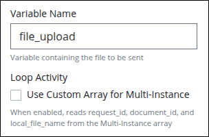
In the Variable Name setting, enter the Request variable name that stores the documents for processing without using mustache syntax, then press Enter.
Otherwise, instead of entering a variable name, enable Loop Activity to use a custom array configured in the multi-instance settings.
Configure the Smart Extract Model
The Smart Extract connector includes configuration options that allow Process Designers to define how documents are extracted, validated, and routed for human review when necessary.
Follow these steps to use the appropriate extraction model:
Expand the Configuration panel if it is not presently expanded, and then locate the Select Model Type setting.
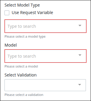
If not selected Use Request Variable, do the following:
In the Select Model Type, select the extraction model type.
In the Model, select the Smart Extract model to apply.
Select the Use Request Variable option, and enter a request variable that contains a reference to the model type and the Smart Extract model in Select Model Type and Model. Reference this Request variable without using mustache syntax.
In Select Validation, select a validation rule to Define the condition used to evaluate extraction confidence and completeness.
Loop Activity Panel Settings
Use the Loop Activity panel settings to specify how to run multiple instances of this object. The following loop modes are available:
No Loop Mode
Select the No Loop Mode option to perform this object's function only once.
Follow these steps to specify characteristics to perform multiple instances of the object:
Select the object from the Process model. Panels to configure this object display.
Expand the Loop Activity panel. By default, the Loop Mode setting is set to No Loop Mode and the function is performed only once.
.png "image(135).png")
Loop
Select the Loop option to sequentially repeat this object's function multiple times until an exit condition is True. This is useful when a function should be performed multiple times with the same set of data, such as, processing a credit card payment. This loop mode has the following characteristics:
The object's function is repeated until the exit condition is
Trueor the maximum iterations limit is reached.At any given time, only one instance of the object is active. The subsequent instance does not begin until the current instance completes.
The same exit condition evaluates at the end of each instance; however, value(s) of the Request variable(s) used in the exit condition can change during an instance resulting in the exit condition to eventually evaluate as
True.If any one instance of that function does not complete, workflow pauses.
All active instances are terminated if an interrupting boundary-type event object triggers.
An object configured in this mode shows the Loop icon
.png "image(137).png") in Process Modeler.
in Process Modeler.
Follow these steps to specify characteristics to perform multiple instances of the object:
Select the object from the Process model in which to specify multiple instance characteristics. Panels to configure this object display.
Expand the Loop Activity panel to display the Loop Mode Setting.
From the Loop Mode setting, select the Loop option. The settings for this loop mode display:
.png "image(136).png")
In the Maximum Iterations setting, enter an integer value representing the maximum number of times this Task should be performed.
In the Exit Condition setting, enter a condition in FEEL syntax. When this condition is True the loop activity is halted.
Multi-instance(Parallel)
Select the Multi-instance (Parallel) option to perform this object's Task multiple times in parallel a fixed number of times. This is useful when performing any action in bulk, such as sending an email to several people. This loop mode has the following characteristics:
Instances of the object are governed by the size of an array-type Request variable where a new instance is created for each item in this variable. For example, an array with 10 items will create 10 parallel instances of this function that each contains data from its respective array index.
All instances begin simultaneously when this object triggers; however, they perform their function independently of each other.
The function as a whole completes when all instances are complete.
The output from each instance can either be saved in the source Request variable or a new array-type Request variable.
All active instances terminate if an interrupting boundary-type event object triggers.
A object configured in this mode shows the Multi-instance (Parallel) icon in Process Modeler.
Follow these steps to specify characteristics to perform multiple instances of the object:
Select the object from the Process model in which to specify multiple instance characteristics. Panels to configure this object display.
Expand the Loop Activity panel to display the Loop Mode Setting.
From the Loop Mode setting, select the Multi-instance (Parallel) option. The settings for this loop mode display:
.png "image(138).png")
In the Request Variable Array setting, enter the name of an array-type Request variable. The size of this array will determine how many times this loop iterates.
In the Output Data Variable setting, enter the name of an array-type Request variable in which to store the results of all instances. Each instance of the loop saves to a separate JSON object within the array of the specified Request variable. If the Output Data Variable setting is not configured, then the output data replaces the source data in the Request Variable Array.
Multi-instance(Sequential)
Select the Multi-instance (Sequential) option to perform this object's function multiple times sequentially a fixed number of times or until an exit condition is True. This is useful when sequentially repeating a function multiple times but with a different set of data each time. This loop mode has the following characteristics:
Instances of the function are governed by the size an array-type Request variable where a new instance is created for each item in this variable. For example, an array with 10 items will create 10 parallel instances of this function that each contains data from its respect array index.
At any given time, only one instance of the function is active. The subsequent instance does not begin until the current instance completes.
At the end of each instance an exit condition evaluates and the loop activity halts if the exit condition is True.
The function as a whole completes when all instances are complete.
The output from each instance can either be saved in the source Request variable or a new array-type Request variable.
All active instances terminate if an interrupting boundary-type event object triggers.
A object configured in this mode shows the Multi-instance (Sequential) iconin Process Modeler.
Follow these steps to specify characteristics to perform multiple instances of the object:
Select the object from the Process model in which to specify multiple instance characteristics. Panels to configure this object display.
Expand the Loop Activity panel to display the Loop Mode Setting.
From the Loop Mode setting, select the Multi-instance (Sequential) option. The settings for this loop mode display:
.png "image(139).png")
In the Request Variable Array setting, enter the name of an array-type Request variable. The size of this array will determine how many times this loop iterates.
In the Exit Condition setting, enter a condition in FEEL syntax. When this condition is True the loop activity is halted.
In the Output Data Variable setting, enter the name of an array-type Request variable in which to store the results of all instances. Each instance of the loop saves to a separate JSON object within the array of the specified Request variable. If the Output Data Variable setting is not configured, then the output data replaces the source data in the Request Variable Array.
HITL Assignee Panel Settings
Configure Human-in-the-Loop Validation
Enable Human-in-the-Loop (HITL) behavior to introduce a manual review step when validation rules fail.
Click the Human in the Loop toggle to enable the behavior.
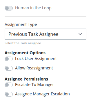
From the Assignment Type drop-down menu, select one of the following options:
Users / Groups: Select this option to assign the connector to a specified user or to a group member.
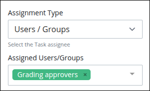
From the Assigned Users/Groups drop-down menu, select one or more users and/or groups for this connector. The connector is assigned following this protocol:
One user: The connector is assigned to the selected user.
One or more users and/or group(s): The connector is assigned randomly to one of those users or group members. The exception is if the Self Service toggle key is enabled, then the connector remains unassigned, in a queue, for one of those users to self-assign from the Self Service page.
Previous Task Assignee: Select this option to assign the connector to the assignee of the previous task.
Request Starter: Select this option to assign the connector to the Request starter. This is the default option.
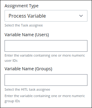
Process Variable: Select this option to assign the connector determined by the value of a Request variable. The entered variable(s) may be one or both of the following:
Variable Name (Users): In this setting, enter the Request variable that contains the user ID(s) for one or more users. If more than one user ID is included the Request variable's value, then the connector is assigned randomly to one of those users. The exception is if the Self Service toggle key is enabled, then the connector remains unassigned, in a queue, for one of those users to self-assign from the Self Service page.
Variable Name (Groups): In this setting, enter the Request variable that contains a group ID(s). The connector is assigned randomly to one of the group members. The exception is if the Self Service toggle key is enabled, then the connector remains unassigned, in a queue, for one of those users to self-assign from the Self Service page.
Rule Expression: Select this option to assign the connector's assignee using one or more rules. The rule expressions follow the Friendly Enough Expression Language (FEEL) syntax described in Expression Syntax Components.
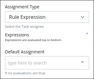
Each rule can only have one expression, but by using logical operators multiple conditions can be specified in that expression. You may use multiple rules to better confine the condition(s), and you may use Magic Variables in your expression. To add an expression, click the add
 button.
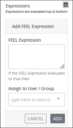
Follow these steps to define an expression:
In the FEEL Expression setting, enter or edit the expression using the syntax components described in Expression Syntax Components, and then press Enter.
From the Assign to User/Group drop-down menu, select the user or group to assign the connector to when the FEEL Expression evaluates to True.
From the Default Assignment drop-down menu, select a user or group to assign that connector to if none of the expressions evaluate as True.
Process Manager: Select Process Manager to assign the connector to the Process Manager. Ensure to configure the Process Manager for this Process.
In the Assignment Options, do the following:
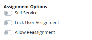
Enable the Self Service toggle to allow group members to self-assign the connector from a queue. This option is only available if the Assignment Type is set to Users / Groups, Process Variable, or Rule Expression.
Enable the Lock User Assignment toggle to ensure the connector is reassigned to the same user if the workflow returns to it. This is useful when the original assignee may need to clarify or update information they previously submitted.
Enable the Allow Reassignment toggle key to allow the connector assignee to reassign the connector if necessary. If the Allow Reassignment option is enabled, the Reassign button displays in the connector summary to allow for connector reassignment.
In the Assignee Permissions, do the following:
Enable the Escalate to Manager toggle key to assign that connector to the manager of the connector assignee. An Administrator can configure the manager for each user in their user account.
Enable the Allow Manager Escalation toggle key to automatically reassign this connector to the connector assignee's manager. An Administrator can configure the manager for each user in their user account.
If you enable the Allow Reassignment option, make sure the connector is assigned to multiple users or to a group. Otherwise, even though the Reassign button will appear in the connector summary, the assignee will have no available users to reassign the connector to.
Advanced Panel Settings
Edit the Node's Identifier Value
A Process node represents a component of a Process model, whether that is a BPMN element or a connector. Process Modeler automatically assigns a unique value to each Process node added to a Process model. A Process node's identifier value can be changed if it is unique to all other nodes in the Process model, including the Process model's identifier value.
All identifier values for all nodes in the Process model must be unique.
Follow these steps to edit the identifier value for an Smart Extract connector:
Select the Smart Extract connector from the Process model in which to edit its identifier value.
Ensure that the Configuration panel displays. If not, show it. Panels to configure this element display.
Expand the Advanced panel if it is not presently expanded. The Node Identifier setting displays. This is a required setting.
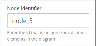
In the Node Identifier setting, edit the Smart Extract connector's identifier to a unique value from all nodes in the Process model and then press Enter.