Use Decision Task connectors to run Decision Tables in your Processes. Specify which Decision Table(s) to run, thereby evaluating their business rules, and then map how data is passed between process variables and Decision Table variables.
Decision Task connectors immediately evaluate the business rules within a specified Decision Table, thereby affecting process routing in real time with the current conditions and outcomes for all decisions in that Decision Table.
Add a Decision Task Connector to the Process Model
Permissions
Processes: Edit Processes
Processes: View Processes
See the Process permissions or ask your Administrator for assistance.
Your user account or group membership must have the following permissions to configure a Decision Task connector to the Process model unless your user account has the Make this user a Super Admin setting selected:
Processes: Edit Processes
Processes: View Processes
See the Process permissions or ask your Administrator for assistance.
Add a Decision Task connector from one of the following locations in Process Modeler:
Object Panel: Located to the left of the Process Modeler canvas, the Object Panel contains various process model objects.
Object Bar: Located at the bottom of the Process Modeler canvas, the Object Bar contains pinned Process model objects for quick access.
Follow these steps to add a Decision Task connector from the Object panel to the Process model:
Ensure that the Object panel is visible on the left. If not, click the Add icon
 from the Object bar at the bottom.
Click the Decision Task object
 from the Object panel to select it.
Click the location in the Process model to place this connector. Follow these guidelines when placing this object:
If your process has a Pool object, the Decision Task object cannot be placed outside of the Pool.
To place this object between two existing objects, follow these instructions.
Follow these steps to add a Decision Task connector from the Object bar to the Process model:
Ensure that the Decision Task object
 is pinned to the Object bar. If not, see instructions to pin it it.
In the Object bar at the bottom center, click the object's icon.
Click the location in the Process model to place this element. Follow these guidelines when placing this object:
If your process has a Pool object, the Decision Task object cannot be placed outside of the Pool.
To place this object between two existing objects, follow these instructions.
Add boundary events
- Boundary Timer Event element
- Boundary Error Event element
- Boundary Signal Event element
- Boundary Conditional Event element
- Boundary Message Event element
Preview the Decision Table
After a Decision Task is added to a Process model and a Decision table has been selected, you may preview the Decision Table to verify its contents. If multiple Decision Tables have been selected, the preview shows the first table.
Select the Decision Task connector. Available menu options display above the selected element.
Click the Preview icon
 . A preview window displays and shows the Decision Table.
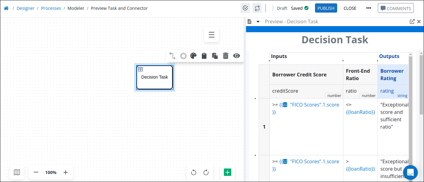
From the Preview window, you can do the following:
Click the icon
 to open the Decision Table Editor to edit the Decision Table.
Click the icon
 to close the preview window.
Settings
The Decision Task connector has the following properties:
Configuration panel
Loop Activity panel
Decision Tables panel
Variable Mapping panel
Advanced panel
Configuration Panel
Edit the Connector Name
A connector name is a human-readable reference for a Process model control. Process Modeler automatically assigns the name of a Process model connector with its connector type. However, a connector's name can be changed.
Follow these steps to edit the name for a Decision Task connector:
Select the Decision Task connector from the Process model in which to edit its name.
Ensure that the Configuration panel displays. If not, show it. The Name setting displays.
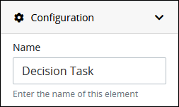
In the Name setting, edit the selected connector's name and then press Enter.
Add a Placeholder for the Slideshow Mode
The Slideshow Mode makes it easy for process designers to share the design of a process with all stakeholders, regardless of whether they have access to the ProcessMaker Platform. For more information on how to create slideshows for a process, see Slideshow Mode.
Follow these steps to add a placeholder image for the Slideshow Mode:
Select an object from the Process model.
Click the
.png "image(250).png") icon to view the Configuration panel.
icon to view the Configuration panel.From the Placeholder for Slideshow section, click on the +Drag or click here button to upload an image.
.png "image(251).png")
A preview of the image will display, and the configuration will be auto-saved.
.png "image(252).png")
The uploaded image will be shown for this task the next time the slideshow is viewed.
Size of a placeholder image for slideshows must less than 2 MB.
Image files with PNG, JPG, JPEG, and GIF extensions are supported.
The Slideshow Mode makes it easy for process designers to share the design of a process with all stakeholders, regardless of whether they have access to the ProcessMaker Platform. For more information on how to create slideshows for a process, see Slideshow Mode.
Follow these steps to add a placeholder image for the Slideshow Mode:
Select an object from the Process model.
Click the icon to view the Configuration panel.
From the Placeholder for Slideshow section, click on the +Drag or click here button to upload an image.
Loop Activity Panel Settings
Use the Loop Activity panel settings to specify how to run multiple instances of this object. The following loop modes are available:
No Loop Mode
Select the No Loop Mode option to perform this object's function only once.
Follow these steps to specify characteristics to perform multiple instances of the object:
Select the object from the Process model. Panels to configure this object display.
Expand the Loop Activity panel. By default, the Loop Mode setting is set to No Loop Mode and the function is performed only once.
.png "image(135).png")
Loop
Select the Loop option to sequentially repeat this object's function multiple times until an exit condition is True. This is useful when a function should be performed multiple times with the same set of data, such as, processing a credit card payment. This loop mode has the following characteristics:
The object's function is repeated until the exit condition is
Trueor the maximum iterations limit is reached.At any given time, only one instance of the object is active. The subsequent instance does not begin until the current instance completes.
The same exit condition evaluates at the end of each instance; however, value(s) of the Request variable(s) used in the exit condition can change during an instance resulting in the exit condition to eventually evaluate as
True.If any one instance of that function does not complete, workflow pauses.
All active instances are terminated if an interrupting boundary-type event object triggers.
An object configured in this mode shows the Loop icon
.png "image(137).png") in Process Modeler.
in Process Modeler.
Follow these steps to specify characteristics to perform multiple instances of the object:
Select the object from the Process model in which to specify multiple instance characteristics. Panels to configure this object display.
Expand the Loop Activity panel to display the Loop Mode Setting.
From the Loop Mode setting, select the Loop option. The settings for this loop mode display:
.png "image(136).png")
In the Maximum Iterations setting, enter an integer value representing the maximum number of times this Task should be performed.
In the Exit Condition setting, enter a condition in FEEL syntax. When this condition is True the loop activity is halted.
Multi-instance(Parallel)
Select the Multi-instance (Parallel) option to perform this object's Task multiple times in parallel a fixed number of times. This is useful when performing any action in bulk, such as sending an email to several people. This loop mode has the following characteristics:
Instances of the object are governed by the size of an array-type Request variable where a new instance is created for each item in this variable. For example, an array with 10 items will create 10 parallel instances of this function that each contains data from its respective array index.
All instances begin simultaneously when this object triggers; however, they perform their function independently of each other.
The function as a whole completes when all instances are complete.
The output from each instance can either be saved in the source Request variable or a new array-type Request variable.
All active instances terminate if an interrupting boundary-type event object triggers.
A object configured in this mode shows the Multi-instance (Parallel) icon in Process Modeler.
Follow these steps to specify characteristics to perform multiple instances of the object:
Select the object from the Process model in which to specify multiple instance characteristics. Panels to configure this object display.
Expand the Loop Activity panel to display the Loop Mode Setting.
From the Loop Mode setting, select the Multi-instance (Parallel) option. The settings for this loop mode display:
.png "image(138).png")
In the Request Variable Array setting, enter the name of an array-type Request variable. The size of this array will determine how many times this loop iterates.
In the Output Data Variable setting, enter the name of an array-type Request variable in which to store the results of all instances. Each instance of the loop saves to a separate JSON object within the array of the specified Request variable. If the Output Data Variable setting is not configured, then the output data replaces the source data in the Request Variable Array.
Multi-instance(Sequential)
Select the Multi-instance (Sequential) option to perform this object's function multiple times sequentially a fixed number of times or until an exit condition is True. This is useful when sequentially repeating a function multiple times but with a different set of data each time. This loop mode has the following characteristics:
Instances of the function are governed by the size an array-type Request variable where a new instance is created for each item in this variable. For example, an array with 10 items will create 10 parallel instances of this function that each contains data from its respect array index.
At any given time, only one instance of the function is active. The subsequent instance does not begin until the current instance completes.
At the end of each instance an exit condition evaluates and the loop activity halts if the exit condition is True.
The function as a whole completes when all instances are complete.
The output from each instance can either be saved in the source Request variable or a new array-type Request variable.
All active instances terminate if an interrupting boundary-type event object triggers.
A object configured in this mode shows the Multi-instance (Sequential) iconin Process Modeler.
Follow these steps to specify characteristics to perform multiple instances of the object:
Select the object from the Process model in which to specify multiple instance characteristics. Panels to configure this object display.
Expand the Loop Activity panel to display the Loop Mode Setting.
From the Loop Mode setting, select the Multi-instance (Sequential) option. The settings for this loop mode display:
.png "image(139).png")
In the Request Variable Array setting, enter the name of an array-type Request variable. The size of this array will determine how many times this loop iterates.
In the Exit Condition setting, enter a condition in FEEL syntax. When this condition is True the loop activity is halted.
In the Output Data Variable setting, enter the name of an array-type Request variable in which to store the results of all instances. Each instance of the loop saves to a separate JSON object within the array of the specified Request variable. If the Output Data Variable setting is not configured, then the output data replaces the source data in the Request Variable Array.
Decision Tables
The Decision Task has multiple settings in the Decision Tables panel:
Select Decision Table(s)
You can select one of more Decision Tables to run in a Decision Task. Follow these steps to select the Decision Table(s).
Expand the Decision Tables panel. The Tables to run setting displays.
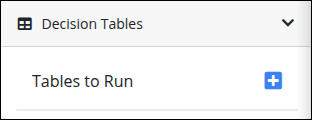
Click the
 icon to add a Decision Table.
From the Select a Table drop-down menu, select a Decision Table.
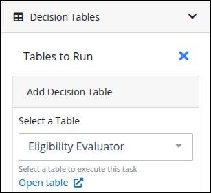
Optionally, click the Open table link to view and/or edit your selected Decision Table.
If no Decision Tables exist, the Select a Table drop-down menu contains no options.
Select a Hit Policy
New in Spring 2025
This feature is available in the Spring 2025 release.
From the Hit Policy setting, select one of the following policies.
Single: Returns a single result based on the selected single-hit policy.
First
Evaluates rules sequentially and returns the output of the first satisfied rule, ignoring the rest. Users can reorder rules to control priority.
Unique
Ensures that only one rule is satisfied and returns the output of a single satisfied rule. If multiple rules are satisfied, the decision table returns an error.
Any
Returns the output when multiple rules are satisfied, but only if they all produce the same result. If conflicting outputs exist, the decision table fails.
Multiple: Evaluates all matching rules and aggregates the results based on the selected multi-hit policy.
Collect Sum
Returns the sum of the outputs from all satisfied rules. Outputs must be numerical values or durations.
Collect Min
Returns the smallest output value among all satisfied rules. Outputs must be comparable, such as numbers, durations, strings, dates, or times.
Collect Max
Returns the largest output value among all satisfied rules. Outputs must be comparable, such as numbers, durations, strings, dates, or times.
Collect Count
Returns the total count of outputs of all satisfied rules. Each rule's output can be of any type, but the decision table always returns a number.
Rule order
Returns the outputs of all satisfied rules in a list, maintaining their evaluation order.
Optionally, configure a Friendly Enough Expression Language (FEEL) expression that evaluates if the Decision Table should run prior to evaluating any decisions in it. To do so, do the following:
Enable the Execute Conditionally setting.
Enter the expression that must evaluate as
TRUEfor this Decision Table to evaluate its business rules.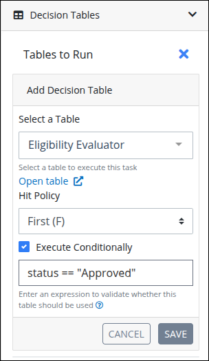
Click Save. The selected Decision Table displays in the Tables to run setting. If no conditions are specified to run this Decision Table, Always displays below the Decision Table name. Otherwise, the conditional expression displays.
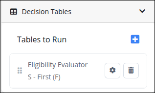
Click the gear icon to edit the Decision Table configuration.
Click the trash icon to delete the table. A confirmation message displays.
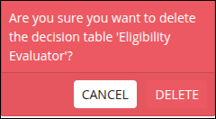
Click Delete.
Variable Mapping
After selecting one or more Decision Table, map how decision variables in the selected Decision Table map to process variables. Mapping involves two procedures:
Map Outbound Data from the process to the Decision Table
Follow these steps to map outbound data from the process to the Decision Table:
Select the Decision Task from the Process model.
Ensure that the Configuration panel displays. If not, show it. Panels to configure this element display.
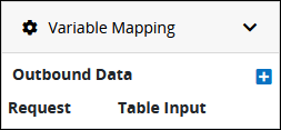
Expand the Variable Mapping panel. The Outbound Data setting displays.
Click the
icon to expand the Outbound Data setting. The Map to Column setting displays. 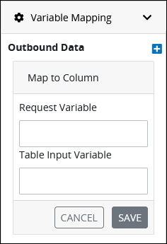
In the Request Variable setting, enter the name of the Request variable that sends data to the decision input variable of the Decision Table.
In the Table Input Variable setting, enter the decision input variable's name that receives the Request variable data. Ensure to enter the decision input variable's name, not its label.
Click Save. The mapped variables display in the Outbound Data setting.
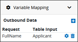
Optionally do one of the following to edit or delete a mapped outbound data variable pairing:
Edit a mapped outbound data variable pairing: Click the
 icon for the mapped variable pairing in which to change its settings.
Delete a mapped outbound data variable pairing: Click the
 icon for the mapped variable pairing in which to delete. A confirmation message displays. Click Confirm to delete the mapped variable pairing.
Repeat steps 3 through 7 as necessary for each Request variable to map to a Decision Table.
Map Decision Table Data to the process After Evaluating Business Rules
Follow these steps to map Decision Table output variable data to process variables after evaluating business rules:
Select the connector from the Process model in which to map variable data routing.
Ensure that the Configuration panel displays. If not, show it. Panels to configure this element display.
Expand the Variable Mapping panel if it is not already expanded. The Outbound Data and Response Mapping settings display.
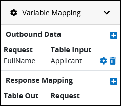
From the Response Mapping setting, click the
icon to expand the Outbound Data setting. The Configured Returned Data setting displays. 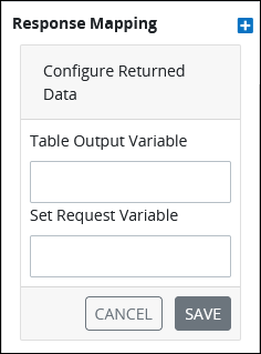
In the Table Output Variable setting, enter the name of the output decision variable from the Decision Table that sends data to the Request variable. Ensure to enter the decision output variable's name, not its label.
In the Set Request Variable setting, enter the Request variable's name that receives the output decision variable data.
Click Save. The mapped variables display in the Response Mapping setting.
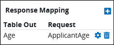
Optionally do one of the following to edit or delete a mapped outbound data variable pairing:
Edit a mapped variable response pairing: Click the
icon for the mapped variable pairing in which to change its settings.Delete a mapped variable variable pairing: Click the
icon for the mapped variable pairing in which to delete. A confirmation message displays. Click Confirm to delete the mapped variable pairing.
Repeat steps 3 through 7 as necessary for each Request variable to map to a Decision Table.
Advanced Panel Settings
Edit the Node's Identifier Value
A Process node represents a component of a Process model, whether that is a BPMN element or a connector. Process Modeler automatically assigns a unique value to each Process node added to a Process model. A Process node's identifier value can be changed if it is unique to all other nodes in the Process model, including the Process model's identifier value.
All identifier values for all nodes in the Process model must be unique.
Follow these steps to edit the identifier value for a Decision Task connector:
Select the Decision Task connector from the Process model in which to edit its identifier value.
Ensure that the Configuration panel displays. If not, show it. Panels to configure this element display.
Expand the Advanced panel if it is not presently expanded. The Node Identifier setting displays. This is a required setting.
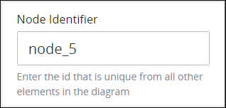
In the Node Identifier setting, edit the Decision Task connector's identifier to a unique value from all nodes in the Process model and then press Enter.