Data Connectors allow Process Designers too interact with a data source within a process. Use a Data Connector in your Process models in the following ways:
Access Collections: From your Process model, interact with any Collection in your ProcessMaker Platform instance, including viewing, creating, updating, and/or delete records in a selected Collection. By default, each Collection has a corresponding Data Connector when it is created. Incorporate Collection record data into your Process model so you can make business decisions using it. Likewise, automatically change records in a Collection during a Request when workflow routing conditions are met.
Access third-party data sources: Similarly to Collections, interact with third-party data sources such as Application Program Interfaces (APIs). Reference data from that API, then incorporate it into your Process's Request data. Incorporating data from external data sources helps you make business decisions from information outside of your ProcessMaker Platform instance.
Add a Data Connector to the Process Model
Permissions
Your user account or group membership must have the following permissions to configure a Data Connector connector to the Process model unless your user account has the Make this user a Super Admin setting selected:
Processes: Edit Processes
Processes: View Processes
See the Process permissions or ask your Administrator for assistance.
Add a Data Connector from one of the following locations in Process Modeler:
Object Panel: Located to the left of the Process Modeler canvas, the Object Panel contains various process model objects.
Object Bar: Located at the bottom of the Process Modeler canvas, the Object Bar contains pinned Process model objects for quick access.
Follow these steps to add a Data Connector from the Object panel to the Process model:
Ensure that the Object panel is visible on the left. If not, click the Add icon
 from the Object bar at the bottom.
Click the Data Connector object
 from the Object panel to select it.
Click the location in the Process model to place this connector. Follow these guidelines when placing this object:
If your process has a Pool object, the Data Connector object cannot be placed outside of the Pool.
To place this object between two existing objects, follow these instructions.
Follow these steps to add a Data Connector from the Object bar to the Process model:
Ensure that the Data Connector object
 is pinned to the Object bar. If not, see instructions to pin it it.
In the Object bar at the bottom center, click the object's icon.
Click the location in the Process model to place this element. Follow these guidelines when placing this object:
If your process has a Pool object, the Data Connector object cannot be placed outside of the Pool.
To place this object between two existing objects, follow these instructions.
Add boundary events
- Boundary Timer Event element
- Boundary Error Event element
- Boundary Signal Event element
- Boundary Conditional Event element
- Boundary Message Event element
Settings
The Data Connector has the following panels that contain settings:
Data Connector panel
Loop Activity panel
Callback panel
Error Handling panel
Documentation panel
Advanced panel
Data Connector Panel Settings
The Data Connector has the following settings in the Data Connector panel:
Edit the Connector Name
A connector name is a human-readable reference for a Process model control. Process Modeler automatically assigns the name of a Process model connector with its connector type. However, a connector's name can be changed.
Follow these steps to edit the name for a Data Connector:
Select the Data Connector from the Process model in which to edit its name.
Ensure that the Configuration panel displays. If not, show it. The Name setting displays.
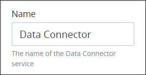
In the Name setting, edit the selected connector's name and then press Enter.
Select the Data Connector
The Data Connector uses a Data Connector that is configured to interact with a data source, such as a Collection or a third-party Application Program Interface (API). A Data Connector must already exist before it can be selected for use in a Data Connector. Each Data Connector is already configured with which data source it interacts.
Collections automatically create a Data Connector when the Collection is created. Data Connectors created from a Collection by default have the same name as the Collection that it references.
Follow these steps to select the Data Connector the Data Connector uses:
Select the Data Connector from the Process model in which to specify the Data Connector to reference.
Ensure that the Configuration panel displays. If not, show it. Panels to configure this element display.
Expand the Data Connector panel if it is not presently expanded, and then locate the Select a Data Connector setting.
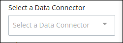
From the Select a Data Connector drop-down menu, select which Data Connector the Data Connectoruses.
Select which Resource the Data Connector uses to interact with the data source.
Ensure to select which of the Data Connector's Resources interacts with the data source to properly configure the Data Connector.
Select the Resource the Data Connector Uses to Interact with the Data Source
Each Data Connector contains at least one Resource. These Resources are configured from the Data Connector itself. A Resource is an action the Data Connector uses to interact with the data source. The Data Connector uses a Resource to interact with the data source. These Resources may interact with Collection records, Application Program Interfaces (APIs), or other data source types. After a Data Connector has been selected from the Select a Data Connector setting, select the Resource from that Data Connector the Data Connector uses to interact with the data source.
Data Connectors created from Collections use a default set of Resources. See Resources for Collections.
Follow these steps to select which Resource the Data Connector uses:
Select the Data Connector from the Process model in which to select the resource the Data Connector uses.
Ensure that the Configuration panel displays. If not, show it. Panels to configure this element display.
Expand the Data Connector panel if it is not presently expanded, and then locate the Select a Data Connector setting. Ensure that a Data Connector is selected from the Select a Data Connector setting. If not, see Select the Data Connector.
Locate the Select a Resource setting.
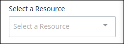
From the Select a Resource drop-down menu, select which Resource the Data Connector uses to interact with the data source.
Add Outbound Properties to Send Data to the Data Source
Configure to which data properties the Data Connector sends to the data source, whether that be an Application Program Interface (API) or Collection to which the Data Connector is configured to interact.
Ensure that you have configured the following before configuring outbound properties, in this order:
Outbound data may be sent to each parameter, header, or body configured in the Data Connector once.
Follow these steps to configure outbound properties:
Select the Data Connector from the Process model in which to add outbound properties.
Ensure that the Configuration panel displays. If not, show it. Panels to configure this element display.
Expand the Data Connector panel if it is not presently expanded, and then locate the Outbound Configuration. Ensure that a Data Connector and a Resource are selected from the Select a Data Connector and Select a Resource settings, respectively. If not, see Select the Data Connector and Select the Resource, in that order.
Locate the Outbound Configuration setting.
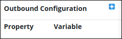
Locate and click the
 icon. The Add Option screen displays.
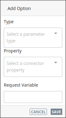
From the Type drop-down menu, select from which type of data configured for the selected Resource in which to interact with its data:
Param: Select the Param option to select a parameter configured with the selected Resource. If no parameters are configured for the selected Resource, Not available displays.
Header: Select the Header option to select a header configured with the selected Resource. If no headers are configured for the selected Resource, Not available displays.
Body: Select the Body option to select the body configured for the selected Resource that is typically used in PUT and POST methods. If the selected Resource is not configured to include a body, Not available displays.
From the Property drop-down menu, select a property configured for the selected type from the selected resource. If no properties are configured for the selected type in that Resource, Not available displays.
In the Request Variable setting, enter using mustache syntax the Request variable name to use that variable's value when the Resource calls the data source. If the Request Variable setting value is not contained in mustache syntax, the Data Connector uses the literal string during its Resource call.
Click Save.
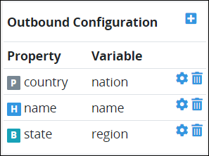
Each outbound configuration to a data source property displays in the Outbound Configuration setting. An icon to the left of each outbound configuration represents its property type:
P: The P icon represents an outbound configuration for a parameter property type.
H: The H icon represents an outbound configuration for a header property type.
B: The B icon represents an outbound configuration for a body property type.
Map Data from the Data Source to the Request's JSON Data Model
Configure how data from the data source integrates with Request data.
Ensure that you have configured the following before configuring outbound properties, in this order:
The procedure to integrate the data source's data to the Request JSON data model is called response mapping: specifying into which Request variable to store the data source's data. The Data Connector may be configured with response mapping, whereby a specified source name in the body or header of the data source response's is mapped to store that value in a specified Request variable. By relying on the Data Connector's response mapping, the Process designer only needs to select the Request variable name as mapped in the Data Connector's response without knowing technical details for this mapping.
Each JSON object contains a key name that references the JSON object, and the value for that key. If the JSON object already exists in a Request's JSON data model, then the Data Connector overwrites the existing JSON object value with that from the data source. If the JSON object(s) to map the data source data does not exist, then the Data Connector adds the JSON data object(s) to that Request's JSON data model.
Follow these steps to specify the Request JSON data object(s) to which to map the data source's data:
Select the Data Connector from the Process model to map the data source's data to the Request JSON object(s).
Ensure that the Configuration panel displays. If not, show it. Panels to configure this element display.
Expand the Data Connector panel if it is not presently expanded. The Response Mapping setting displays.
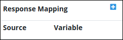
Click the
icon to add a JSON object to which to map data from the data source. The Source and Set to Request Variable settings display to add the JSON source name and its variable, respectively, for the JSON object. 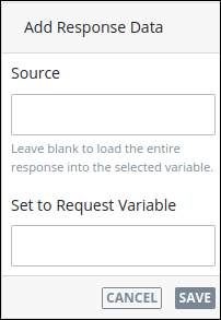
In the Source setting, enter the name of the source from which to store the response. If the source is from Request data, such as from a Collection, the source name is
data.datais the name of the JSON object that stores all data for each Request. However, the Source setting corresponds with how the Data Connector maps the data response: by selecting a mapped Request variable from the Set to Request Variable setting below, its corresponding source name displays in the Source setting. Optionally, specify the source name as a Request variable using mustache syntax.In the Set to Request Variable setting, enter the Request variable as configured in the Data Connector's response mapping in which to store the data source's response. Optionally, specify the source name as a Request variable using mustache syntax. After doing so, the Source setting displays the source's name configured for that response mapping.
Click Save.
Repeat Steps 4 through 6 for each Request variable to store the data source's response.
Click the Delete icon
to delete a mapped response from the Response Mapping setting.
Loop Activity Panel Settings
Use the Loop Activity panel settings to specify how to run multiple instances of this object. The following loop modes are available:
No Loop Mode
Select the No Loop Mode option to perform this object's function only once.
Follow these steps to specify characteristics to perform multiple instances of the object:
Select the object from the Process model. Panels to configure this object display.
Expand the Loop Activity panel. By default, the Loop Mode setting is set to No Loop Mode and the function is performed only once.
.png "image(135).png")
Loop
Select the Loop option to sequentially repeat this object's function multiple times until an exit condition is True. This is useful when a function should be performed multiple times with the same set of data, such as, processing a credit card payment. This loop mode has the following characteristics:
The object's function is repeated until the exit condition is
Trueor the maximum iterations limit is reached.At any given time, only one instance of the object is active. The subsequent instance does not begin until the current instance completes.
The same exit condition evaluates at the end of each instance; however, value(s) of the Request variable(s) used in the exit condition can change during an instance resulting in the exit condition to eventually evaluate as
True.If any one instance of that function does not complete, workflow pauses.
All active instances are terminated if an interrupting boundary-type event object triggers.
An object configured in this mode shows the Loop icon
.png "image(137).png") in Process Modeler.
in Process Modeler.
Follow these steps to specify characteristics to perform multiple instances of the object:
Select the object from the Process model in which to specify multiple instance characteristics. Panels to configure this object display.
Expand the Loop Activity panel to display the Loop Mode Setting.
From the Loop Mode setting, select the Loop option. The settings for this loop mode display:
.png "image(136).png")
In the Maximum Iterations setting, enter an integer value representing the maximum number of times this Task should be performed.
In the Exit Condition setting, enter a condition in FEEL syntax. When this condition is True the loop activity is halted.
Multi-instance(Parallel)
Select the Multi-instance (Parallel) option to perform this object's Task multiple times in parallel a fixed number of times. This is useful when performing any action in bulk, such as sending an email to several people. This loop mode has the following characteristics:
Instances of the object are governed by the size of an array-type Request variable where a new instance is created for each item in this variable. For example, an array with 10 items will create 10 parallel instances of this function that each contains data from its respective array index.
All instances begin simultaneously when this object triggers; however, they perform their function independently of each other.
The function as a whole completes when all instances are complete.
The output from each instance can either be saved in the source Request variable or a new array-type Request variable.
All active instances terminate if an interrupting boundary-type event object triggers.
A object configured in this mode shows the Multi-instance (Parallel) icon in Process Modeler.
Follow these steps to specify characteristics to perform multiple instances of the object:
Select the object from the Process model in which to specify multiple instance characteristics. Panels to configure this object display.
Expand the Loop Activity panel to display the Loop Mode Setting.
From the Loop Mode setting, select the Multi-instance (Parallel) option. The settings for this loop mode display:
.png "image(138).png")
In the Request Variable Array setting, enter the name of an array-type Request variable. The size of this array will determine how many times this loop iterates.
In the Output Data Variable setting, enter the name of an array-type Request variable in which to store the results of all instances. Each instance of the loop saves to a separate JSON object within the array of the specified Request variable. If the Output Data Variable setting is not configured, then the output data replaces the source data in the Request Variable Array.
Multi-instance(Sequential)
Select the Multi-instance (Sequential) option to perform this object's function multiple times sequentially a fixed number of times or until an exit condition is True. This is useful when sequentially repeating a function multiple times but with a different set of data each time. This loop mode has the following characteristics:
Instances of the function are governed by the size an array-type Request variable where a new instance is created for each item in this variable. For example, an array with 10 items will create 10 parallel instances of this function that each contains data from its respect array index.
At any given time, only one instance of the function is active. The subsequent instance does not begin until the current instance completes.
At the end of each instance an exit condition evaluates and the loop activity halts if the exit condition is True.
The function as a whole completes when all instances are complete.
The output from each instance can either be saved in the source Request variable or a new array-type Request variable.
All active instances terminate if an interrupting boundary-type event object triggers.
A object configured in this mode shows the Multi-instance (Sequential) iconin Process Modeler.
Follow these steps to specify characteristics to perform multiple instances of the object:
Select the object from the Process model in which to specify multiple instance characteristics. Panels to configure this object display.
Expand the Loop Activity panel to display the Loop Mode Setting.
From the Loop Mode setting, select the Multi-instance (Sequential) option. The settings for this loop mode display:
.png "image(139).png")
In the Request Variable Array setting, enter the name of an array-type Request variable. The size of this array will determine how many times this loop iterates.
In the Exit Condition setting, enter a condition in FEEL syntax. When this condition is True the loop activity is halted.
In the Output Data Variable setting, enter the name of an array-type Request variable in which to store the results of all instances. Each instance of the loop saves to a separate JSON object within the array of the specified Request variable. If the Output Data Variable setting is not configured, then the output data replaces the source data in the Request Variable Array.
Callback Panel Setting
Configure how the Data Connector automatically calls back the data source by enabling the Wait for server callback setting with a callback. A callback automates receiving data from the data source, such as a third-party service, and then subsequently sending back data to that data source. The Data Connector monitors for data from the data source via a unique URL that may be stored in a Request variable. Likewise, the data that the Data Connector sends to the data source as a response may be stored in a Request variable. Configure the callback to use GET and/or POST methods to retrieve and/or send data, respectively.
In overview, a callback functions as follows:
A Data Connector interacts with a data source, such as the third-party service Stripe that automates payment services. For example, a Request participant has submitted information for a payment via a Task earlier in that Request.
The Request pauses while the Data Connector waits for the data source to respond. The connector monitors for that response. For example, Stripe responds that the submitted payment is accepted or rejected. The third-party service is the Data Connector's data source.
After the third-party service processes its data and responds to the Data Connector, the connector calls back that data source: the connector may get data or post data to that third-party service.
For example, consider a course enrollment process where each student selects courses for that semester and then must pay for tuition. After enrolling in courses, a Task presents the student with a final invoice and payment options. When the student submits payment, the Request invokes a payment service's Application Program Interface (API), such as Stripe, to verify the payment. Use a Data Connector callback to monitor when the payment service's API verifies the payment information entered by the student. The Request now waits for a response from the payment service's API. The API response returns to a Request variable which can be used to determine next steps in that Request. If the student entered correct payment information and payment is honored, then their course enrollment is confirmed; otherwise the student must re-enter their payment details.
Specify a Data connector's callback to the data source
Follow these steps to specify a Data connector's callback to the data source:
Select the Data Connector from the Process model in which to configure the server callback.
Ensure that the Configuration panel displays. If not, show it. Panels to configure this element display.
Expand the Callback panel if it is not presently expanded. The Wait for server callback setting displays, which is disabled by default.
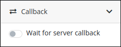
Enable the Wait for server callback option to configure callback settings.
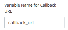
In the Variable Name for Callback URL setting, enter the URL that the data source calls to trigger a callback to the Data Connector. This URL may be stored in a Request variable that must be encapsulated using mustache syntax.
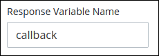
In the Response Variable Name setting, enter the Request variable name within mustache syntax that stores the response from the data source. If the response is JSON, the Request variable stores the response as a JSON object. Otherwise, the Request variable stores the response as text.
In the Accepted methods setting, toggle the GET and/or POST methods as the callback to retrieve and/or send data, respectively.

In the Authentication drop-down menu, select one of the following authentication methods:
None: Select the None option if no authentication is required.
Basic Authentication: Select the Basic Authentication option to configure basic authentication. When selected, the Username and Password settings display.
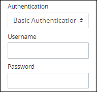
Follow these steps to enter basic authentication credentials:
In the Username setting, enter the username to authenticate with the data source.
In the Password setting, enter the password to authenticate with the data source.
In the Allow Access From setting, enter the server URLs from where the Data Connector accepts callbacks. If a server URL is not included in the Allow Access From setting, then the Data Connector does not accept the response.
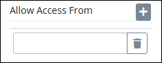
Follow these guidelines to manage server URLs:
Click the Delete
 icon to delete an added server URL.
Click the Add
 icon to add an additional server URL.
After entering a server URL, press Enter.
Error Handling Panel Settings
Follow these guidelines to set how to handle Data Connector runtime errors:
Set how many seconds to wait when an unexpected error occurs during runtime before displaying the error in that Data Connector, thereby causing that Request to be in Error status.
Set how many consecutive attempts to run the Data Connector before displaying a runtime error.
Requests are going to wait the configured number of seconds and consecutive runtime attempts for an unresponsive Data Connector before displaying the error.
Optionally, notify the Process Manager of the Data Connector runtime error via an in-platform or email notification.
Edit the Error Handling settings
Follow these steps to edit the Error Handling settings:
Select the Data Connector from the Process model in which to edit the Error Handling.
Ensure that the Configuration panel displays. If not, show it. Panels to configure this element display.
Expand the Error Handling panel if it is not presently expanded. The Timeout setting displays.
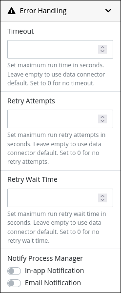
In the Timeout setting, configure how many seconds to wait for an unresponsive Data Connector before declaring a time-out as follows:
Enter the number of seconds. Use the up and down arrows to increase or decrease seconds.
Set
0for no timeout.Leave empty to use the Data Connector default setting.
In the Retry Attempts setting, configure how many times to re-execute the Data Connector if the Data Connector returns a runtime error as follows:
Enter a number. Use the up and down arrows to increase or decrease the number.
Set
0for no retry attempts.Leave empty to use the Data Connector default setting.
In the Retry Wait Time setting, configure how many seconds to wait before attempting a retry as follows:
Enter the number of seconds. Use the up and down arrows to increase or decrease seconds.
Set
0for no timeout.Leave empty to use the Data Connector default setting.
Enable the In-app Notification toggle to notify through the user interface to the Process Manager that there is a Data Connector runtime error.
Enable the Email Notification toggle to notify through an email to the Process Manager that there is a Data Connector execution error.
Documentation Panel Settings
Describe the connector's purpose and how it functions in the Process. This description does not affect Requests for the Process, but may be useful for Process model maintenance such as how the connector is configured. Edit information by using the What-You-See-Is-What-You-Get (WYSIWYG) rich text editor.
A Process's entered documentation displays by selecting the View Documentation icon for that Process.
Edit the Object Documentation
Follow these steps to edit the description for a connector:
Select the connector from the Process model in which to edit its description.
Ensure that the Configuration panel displays. If not, show it. Panels to configure this element display.Panels to configure this connector display.
Expand the Documentation panel if it is not presently expanded. The Description setting displays.
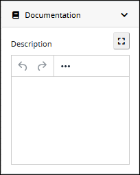
In the Description setting, edit the information to display when viewing documentation for this connector and then press Enter. Alternatively, use the What-You-See-Is-What-You-Get (WYSIWYG) rich text editor to stylize your text by clicking the More icon
 .
. 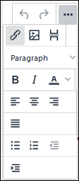
Follow these guidelines to use the WYSIWYG rich text editor to stylize your text:
Undo changes: Click on the
 icon to undo the last action.
Redo changes: Click on the
 icon to redo the last undone action.
Insert/Edit Link: Click on the
 icon to convert the selected text into a hyperlink. Follow these steps to create a hyperlink:
 Select the required text from the Rich Text control.
Click on the
icon. The Insert/Edit Link screen displays. 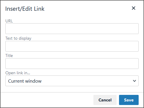
In the URL setting, enter the destination URL.
In the Text to display setting, edit or enter the text displayed in the Rich Text control.
In the Title setting, enter the text to display when a user hovers over the displayed text.
From Open link in… drop-down menu, select one of these options:
New window: Select this option to open the destination page in a new browser window.
Current window: Select this option to open the destination page in the current browser window.
Insert/Edit Image: Click on the Insert/Edit Image icon
 to insert an image. Follow these guidelines:
 Click on the Insert/Edit Image icon
. The Insert/Edit Image screen displays:
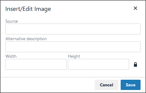
In the Source setting, enter a URL for the image.
In the Alternative Description setting, enter the text to display if the source URL of the image is not accessible.
In the Width setting, enter the maximum width for the image.
In the Height setting, enter the maximum height for the image.
Toggle the Constrain Proportions icon
 to maintain the width-height ratio of the image to its original proportion.
 Click Save.
Insert Page Break for PDF: Click on the Insert Page Break for PDF icon
 to insert a page break when a PDF document is created for this documentation if your browser supports this feature.
 Format text: Follow these guidelines to format text:
Headings: From the Paragraph/Formats menu, select Headings and then select a heading size.
Bold: Do one of the following:
From the editor toolbar, select the
 icon.
icon.From the Paragraph/Formats menu, select Inline and then Bold.
Italics: Do one of the following:
From the editor toolbar, select the
 icon.
icon.From the Paragraph/Formats menu, select Inline and then Italic.
Underline: From the Paragraph/Formats menu, select Inline and then Underline.
Strikethrough: From the Paragraph/Formats menu, select Inline and then Strikethrough.
Superscript: From the Paragraph/ Formats menu, select Inline and then Superscript.
Subscript: From the Paragraph/Formats menu, select Inline and then Subscript.
Code: From the Paragraph/Formats menu, select Inline and then Code.
Paragraph: From the Paragraph/Formats menu, select Blocks and then Paragraph.
Blockquote: From the Paragraph/Formats menu, select Blocks and then Blockquote.
Division: From the Paragraph/Formats menu, select Blocks and then Div.
Preformatted: From the Paragraph/Formats menu, select Blocks and then Pre.
Change text color: Use the Text Color drop-down to change text color. Click on the
 icon. The color palette displays. Do one of the following:
Select one of the color swatches from the color palette. The selected text changes to that color.
Click the
 icon to select a custom color from the Color Picker.
Click the
 icon to reset the text to its default color.
Align text: Follow these guidelines to align text:
Left align: Do one of the following:
From the editor toolbar, use the
 icon to left-align text.
From the Paragraph/Formats menu, select Align and then Left.
Center align: Do one of the following:
From the editor toolbar, use the
 icon to center-align text.
From the Paragraph/Formats menu, select Align and then Center.
Right align: Do one of the following:
From the editor toolbar, use the
 icon to right-align text.
From the Paragraph/Formats menu, select Align and then Right.
Justify: Do one of the following:
From the editor toolbar, use the
 icon to justify text.
 From the Paragraph/Formats menu, select Align and then Justify.
Insert a bullet list: Use the
 icon to format text as a bulleted list.
Insert a numbered list: Use the
 icon to format text as a numbered list.
Indent text: Click on the
 icon to increase text indenting.
Outdent text: Click on the
 icon to decrease text indenting.
Advanced Panel Settings
Edit the Node's Identifier Value
A Process node represents a component of a Process model, whether that is a BPMN element or a connector. Process Modeler automatically assigns a unique value to each Process node added to a Process model. A Process node's identifier value can be changed if it is unique to all other nodes in the Process model, including the Process model's identifier value.
All identifier values for all nodes in the Process model must be unique.
Follow these steps to edit the identifier value for a Data Connector:
Select the Data Connector from the Process model in which to edit its identifier value.
Ensure that the Configuration panel displays. If not, show it. Panels to configure this element display.
Expand the Advanced panel if it is not presently expanded. The Node Identifier setting displays. This is a required setting.
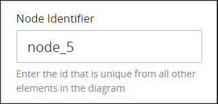
In the Node Identifier setting, edit the Data connector's identifier to a unique value from all nodes in the Process model and then press Enter.