Use the Actions By Email connector in your Process models to automate emails to Request participants that allow them make decisions via email.
When the Actions By Email connector triggers during an in-progress Request, ProcessMaker Platform sends an email from the "no-reply@processmaker.net" email address to one email recipient so that this Request participant can make a decision as part of the Request. For example, this Request participant must make a decision to approve or deny a vacation request or for a purchase. The email recipient receives an email with buttons in the email to easily indicate the decision.
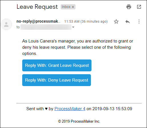
Example email the Actions By Email connector sends to an email recipient
Email design is subject to email client limitations and may not fully support HTML5 or CSS3 specifications. Test your emails in your supported client applications.
While the Actions by Email connector can send the email to multiple email recipients, ProcessMaker Platform registers only the first response. The emails are sent using the Email Default settings, while the response is received using the Actions By Email settings.
After the email recipient clicks a button to indicate the decision, the email client creates an email reply to be delivered to the ProcessMaker Platform instance that used the Actions By Email connector. As indicated in the email reply, do not change anything below the automatically generated response because this response notifies the ProcessMaker Platform instance of the email recipient's decision for Request routing.
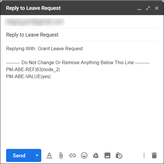
Automatically generated email reply the email recipient sends to the ProcessMaker Platform instance
After the email recipient sends the reply email, ProcessMaker Platform receives the response and uses the indicated decision as part of the Request routing. For example, if you grant a leave request, the Request routes differently than if you deny that leave request.
The comment in the email reply above the indicated line is not preserved when the email reply is sent. This comment displays only for the benefit of the email recipient prior to sending the email reply.
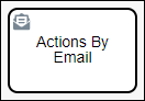
The Actions By Email connector adds the Actions By Email connector below the BPMN 2.0 elements in the panel to the left of the Process Modeler canvas. See the following sections in this topic:
The recipient's email address and/or subject can be specified in one of the following ways when configuring the Actions By Email connector:
Plain text
A Variable Name setting value using mustache syntax, for example
{{ email_recipient }}and{{ email_address }}, respectivelyA Magic Variable value, specifically
{{ _user.fullname }}and{{ _user.email }}, respectively
The Actions By Email connector can send the email to multiple recipients. These email recipients and their email addresses may be referenced from Request data or entered into connector settings.
When an Actions By Email connector triggers during an in-progress Request, ProcessMaker Platform automatically creates an asynchronous child Process: the Actions By Email connector sends the email (the child Process) while simultaneously the in-progress Request continues (the parent Process). In doing so, one of the following occurs:
An error occurs in the email delivery: While attempting to send the email, the Actions By Email connector receives an error. For example, your organization's email server or the email recipient's email server may be down. The child Process receives and sends the error to the parent Process. The child Process ends. Reference the child Process's error from the in-progress Request.
The Actions by Email connector sends the email: The email recipient receives the email while the in-progress Request continues (the parent Process). The child Process ends, but the email recipient may not have responded to the email. If the in-progress Request routes to an Exclusive Gateway element that requires the email recipient's response to evaluate routing, then the in-progress Request remains indefinitely active on the Exclusive Gateway element.
To ensure that Requests do not remain indefinitely active on an Exclusive Gateway element while the Request waits for the email recipient's response, design your Process model to use an Event-Based Gateway element preceding the Exclusive Gateway element that checks the following:
If an Intermediate Timer Event element triggers (after 72 hours, for example), the email recipient has not responded to the email. Thereafter, design in the Process model how to address this, such as sending a subsequent email using the Send Email connector.
If an Intermediate Message Catch Event element triggers instead of the Intermediate Timer Event element, the email recipient sent the response within the allotted time period.
Add an Actions By Email Connector to the Process Model
Permissions
Your user account or group membership must have the following permissions to configure an Actions By Email connector to the Process model unless your user account has the Make this user a Super Admin setting selected:
Processes: Edit Processes
Processes: View Processes
See the Process permissions or ask your Administrator for assistance.
Add an Actions By Email connector from one of the following locations in Process Modeler:
Object Panel: Located to the left of the Process Modeler canvas, the Object Panel contains various process model objects.
Object Bar: Located at the bottom of the Process Modeler canvas, the Object Bar contains pinned Process model objects for quick access.
Follow these steps to add an Actions By Email connector from the Object panel to the Process model:
Ensure that the Object panel is visible on the left. If not, click the Add icon
 from the Object bar at the bottom.
Click the Actions By Email
 from the Object panel to select it.
Click the location in the Process model to place this object. Follow these guidelines when placing this object:
If your process has a Pool object, the Actions By Email object cannot be placed outside of the Pool.
To place this object between two existing objects, follow these instructions.
Follow these steps to add an Actions By Email connector from the Object bar to the Process model:
Ensure that the Actions By Email object
 is pinned to the Object bar. If not, see instructions to pin it it.
In the Object bar at the bottom center, click the object's icon.
Click the location in the Process model to place this element. Follow these guidelines when placing this connector:
If your process has a Pool object, the Actions By Email object cannot be placed outside of the Pool.
To place this object between two existing objects, follow these instructions.
Add boundary events
- Boundary Timer Event element
- Boundary Error Event element
- Boundary Signal Event element
- Boundary Conditional Event element
- Boundary Message Event element
Settings
The Actions by Email connector has the following panels that contain settings:
Configuration panel
Loop Activity panel
Documentation panel
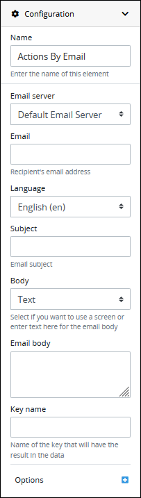
Configuration Panel Settings
The Action By Email connector has multiple settings in the Properties panel.
Configure Actions By Email Connector
Follow these steps to configure an Actions By Email connector:
Select the Actions By Email connector from the Process model in which to configure its settings.
Ensure that the Configuration panel displays. If not, show it. The Actions By Email configuration settings display.
In the Name setting, edit the selected connector's name and then press Enter.
From the Email Server drop-down menu, select which email server that sends the email to the recipient(s). The Default Email Server option is the default. If additional email servers are configured from the Email Default Settings tab in Settings, then additional email server options display in the Email Server drop-down menu.
In the Email setting, enter the email address(es) to which the Actions By Email connector sends an email when this Actions By Email control triggers. You may use the value from a Screen's Variable Name setting as a variable in this setting. For example, if your Process model references a Screen that contains a Line Input control with the Variable Name setting value of
EmailAddressthat the Request participant enters an email address, use mustache syntax{{EmailAddress}}to use that Line Input control's value in the Email setting. Email addresses may be referenced from Request data or entered into the Email setting by using commas (,) between email addresses. You may also use mustache syntax to reference Magic Variables.From the Language drop-down, select one of the following options to specify in which supported natural language the email recipient receives the email:
English (en): The email is in English.
German (de): The email is in German.
Spanish (es): The email is in Spanish.
French (fr): The email is in French.
Use Variable: Use a Request variable to specify which supported language to send the email.
In the Subject setting, enter the subject of the email the Actions By Email connector sends. For example, enter the decision that the email recipient must make in this email.
From the Body setting, select one of the following options:
Text: From the Body drop-down menu, select the Text option to enter the email body text. The Email body setting displays. In the Email body setting, enter the email body text.
Screen: From the Body drop-down menu, select the Screen option to use a Screen to display the email body. The Email body setting displays. From the Email body drop-down menu, select the Display-type Screen to display the email body.
In the Key name setting, enter the name of the key that stores the Actions By Email connector response within the JSON data model of the Request.
In the Options setting, enter the list of options available to the email recipient when making the decision. The options configured here display below the body of the email. Add options in the order they are to display from top to bottom in the email.

Follow these steps to add an option:
Click the plus button
 from the same line where is the Options label. The Add Option screen displays.
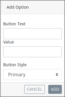
In the Button Text setting, enter the button label displayed to the email.
In the Value setting, enter the internal data name for the option that only the Process Owner views at design time.
In the Button Style setting, select a button style:
Primary: Displays a button with a blue-colored background and white-colored text.
Secondary: Displays a button with a gray-colored background and white-colored text.
Success: Displays a button with a green-colored background and white-colored text.
Info: Displays a button with a teal-colored background and white-colored text.
Warning: Displays a button with a yellow-colored background and black-colored text.
Danger: Displays a button with a red-colored background with white-colored text.
Dark: Displays a button with a black-colored background with white-colored text.
Light: Displays a button with a white-colored background with black-colored text.
Click Add.
Email design is subject to email client limitations and may not fully support HTML5 or CSS3 specifications. Test your emails in your supported client applications.
Loop Activity Panel Settings
Use the Loop Activity panel settings to specify how to run multiple instances of this object. The following loop modes are available:
No Loop Mode
Select the No Loop Mode option to perform this object's function only once.
Follow these steps to specify characteristics to perform multiple instances of the object:
Select the object from the Process model. Panels to configure this object display.
Expand the Loop Activity panel. By default, the Loop Mode setting is set to No Loop Mode and the function is performed only once.
.png "image(135).png")
Loop
Select the Loop option to sequentially repeat this object's function multiple times until an exit condition is True. This is useful when a function should be performed multiple times with the same set of data, such as, processing a credit card payment. This loop mode has the following characteristics:
The object's function is repeated until the exit condition is
Trueor the maximum iterations limit is reached.At any given time, only one instance of the object is active. The subsequent instance does not begin until the current instance completes.
The same exit condition evaluates at the end of each instance; however, value(s) of the Request variable(s) used in the exit condition can change during an instance resulting in the exit condition to eventually evaluate as
True.If any one instance of that function does not complete, workflow pauses.
All active instances are terminated if an interrupting boundary-type event object triggers.
An object configured in this mode shows the Loop icon
.png "image(137).png") in Process Modeler.
in Process Modeler.
Follow these steps to specify characteristics to perform multiple instances of the object:
Select the object from the Process model in which to specify multiple instance characteristics. Panels to configure this object display.
Expand the Loop Activity panel to display the Loop Mode Setting.
From the Loop Mode setting, select the Loop option. The settings for this loop mode display:
.png "image(136).png")
In the Maximum Iterations setting, enter an integer value representing the maximum number of times this Task should be performed.
In the Exit Condition setting, enter a condition in FEEL syntax. When this condition is True the loop activity is halted.
Multi-instance(Parallel)
Select the Multi-instance (Parallel) option to perform this object's Task multiple times in parallel a fixed number of times. This is useful when performing any action in bulk, such as sending an email to several people. This loop mode has the following characteristics:
Instances of the object are governed by the size of an array-type Request variable where a new instance is created for each item in this variable. For example, an array with 10 items will create 10 parallel instances of this function that each contains data from its respective array index.
All instances begin simultaneously when this object triggers; however, they perform their function independently of each other.
The function as a whole completes when all instances are complete.
The output from each instance can either be saved in the source Request variable or a new array-type Request variable.
All active instances terminate if an interrupting boundary-type event object triggers.
A object configured in this mode shows the Multi-instance (Parallel) icon in Process Modeler.
Follow these steps to specify characteristics to perform multiple instances of the object:
Select the object from the Process model in which to specify multiple instance characteristics. Panels to configure this object display.
Expand the Loop Activity panel to display the Loop Mode Setting.
From the Loop Mode setting, select the Multi-instance (Parallel) option. The settings for this loop mode display:
.png "image(138).png")
In the Request Variable Array setting, enter the name of an array-type Request variable. The size of this array will determine how many times this loop iterates.
In the Output Data Variable setting, enter the name of an array-type Request variable in which to store the results of all instances. Each instance of the loop saves to a separate JSON object within the array of the specified Request variable. If the Output Data Variable setting is not configured, then the output data replaces the source data in the Request Variable Array.
Multi-instance(Sequential)
Select the Multi-instance (Sequential) option to perform this object's function multiple times sequentially a fixed number of times or until an exit condition is True. This is useful when sequentially repeating a function multiple times but with a different set of data each time. This loop mode has the following characteristics:
Instances of the function are governed by the size an array-type Request variable where a new instance is created for each item in this variable. For example, an array with 10 items will create 10 parallel instances of this function that each contains data from its respect array index.
At any given time, only one instance of the function is active. The subsequent instance does not begin until the current instance completes.
At the end of each instance an exit condition evaluates and the loop activity halts if the exit condition is True.
The function as a whole completes when all instances are complete.
The output from each instance can either be saved in the source Request variable or a new array-type Request variable.
All active instances terminate if an interrupting boundary-type event object triggers.
A object configured in this mode shows the Multi-instance (Sequential) iconin Process Modeler.
Follow these steps to specify characteristics to perform multiple instances of the object:
Select the object from the Process model in which to specify multiple instance characteristics. Panels to configure this object display.
Expand the Loop Activity panel to display the Loop Mode Setting.
From the Loop Mode setting, select the Multi-instance (Sequential) option. The settings for this loop mode display:
.png "image(139).png")
In the Request Variable Array setting, enter the name of an array-type Request variable. The size of this array will determine how many times this loop iterates.
In the Exit Condition setting, enter a condition in FEEL syntax. When this condition is True the loop activity is halted.
In the Output Data Variable setting, enter the name of an array-type Request variable in which to store the results of all instances. Each instance of the loop saves to a separate JSON object within the array of the specified Request variable. If the Output Data Variable setting is not configured, then the output data replaces the source data in the Request Variable Array.
Documentation Panel Settings
Describe the connector's purpose and how it functions in the Process. This description does not affect Requests for the Process, but may be useful for Process model maintenance such as how the connector is configured. Edit information by using the What-You-See-Is-What-You-Get (WYSIWYG) rich text editor.
A Process's entered documentation displays by selecting the View Documentation icon for that Process.
Edit the Object Documentation
Follow these steps to edit the description for a connector:
Select the connector from the Process model in which to edit its description.
Ensure that the Configuration panel displays. If not, show it. Panels to configure this element display.
Expand the Documentation panel if it is not presently expanded. The Description setting displays.
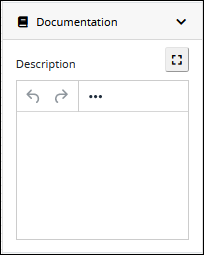
In the Description setting, edit the information to display when viewing documentation for this connector and then press Enter. Alternatively, use the What-You-See-Is-What-You-Get (WYSIWYG) rich text editor to stylize your text by clicking the More icon
 .
. 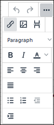
Follow these guidelines to use the WYSIWYG rich text editor to stylize your text:
Undo changes: Click on the
 icon to undo the last action.
Redo changes: Click on the
 icon to redo the last undone action.
Insert/Edit Link: Click on the
 icon to convert the selected text into a hyperlink. Follow these steps to create a hyperlink:
 Select the required text from the Rich Text control.
Click on the
icon. The Insert/Edit Link screen displays. 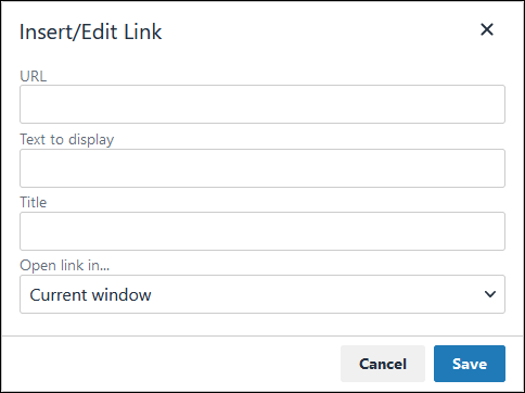
In the URL setting, enter the destination URL.
In the Text to display setting, edit or enter the text displayed in the Rich Text control.
In the Title setting, enter the text to display when a user hovers over the displayed text.
From Open link in… drop-down menu, select one of these options:
New window: Select this option to open the destination page in a new browser window.
Current window: Select this option to open the destination page in the current browser window.
Insert/Edit Image: Click on the Insert/Edit Image icon
 to insert an image. Follow these guidelines:
 Click on the Insert/Edit Image icon
. The Insert/Edit Image screen displays:
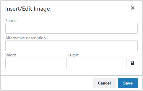
In the Source setting, enter a URL for the image.
In the Alternative Description setting, enter the text to display if the source URL of the image is not accessible.
In the Width setting, enter the maximum width for the image.
In the Height setting, enter the maximum height for the image.
Toggle the Constrain Proportions icon
 to maintain the width-height ratio of the image to its original proportion.
 Click Save.
Insert Page Break for PDF: Click on the Insert Page Break for PDF icon
 to insert a page break when a PDF document is created for this documentation if your browser supports this feature.
 Format text: Follow these guidelines to format text:
Headings: From the Paragraph/Formats menu, select Headings and then select a heading size.
Bold: Do one of the following:
From the editor toolbar, select the
 icon.
icon.From the Paragraph/Formats menu, select Inline and then Bold.
Italics: Do one of the following:
From the editor toolbar, select the
 icon.
icon.From the Paragraph/Formats menu, select Inline and then Italic.
Underline: From the Paragraph/Formats menu, select Inline and then Underline.
Strikethrough: From the Paragraph/Formats menu, select Inline and then Strikethrough.
Superscript: From the Paragraph/ Formats menu, select Inline and then Superscript.
Subscript: From the Paragraph/Formats menu, select Inline and then Subscript.
Code: From the Paragraph/Formats menu, select Inline and then Code.
Paragraph: From the Paragraph/Formats menu, select Blocks and then Paragraph.
Blockquote: From the Paragraph/Formats menu, select Blocks and then Blockquote.
Division: From the Paragraph/Formats menu, select Blocks and then Div.
Preformatted: From the Paragraph/Formats menu, select Blocks and then Pre.
Change text color: Use the Text Color drop-down to change text color. Click on the
 icon. The color palette displays. Do one of the following:
Select one of the color swatches from the color palette. The selected text changes to that color.
Click the
 icon to select a custom color from the Color Picker.
Click the
 icon to reset the text to its default color.
Align text: Follow these guidelines to align text:
Left align: Do one of the following:
From the editor toolbar, use the
 icon to left-align text.
From the Paragraph/Formats menu, select Align and then Left.
Center align: Do one of the following:
From the editor toolbar, use the
 icon to center-align text.
From the Paragraph/Formats menu, select Align and then Center.
Right align: Do one of the following:
From the editor toolbar, use the
 icon to right-align text.
From the Paragraph/Formats menu, select Align and then Right.
Justify: Do one of the following:
From the editor toolbar, use the
 icon to justify text.
 From the Paragraph/Formats menu, select Align and then Justify.
Insert a bullet list: Use the
 icon to format text as a bulleted list.
Insert a numbered list: Use the
 icon to format text as a numbered list.
Indent text: Click on the
 icon to increase text indenting.
Outdent text: Click on the
 icon to decrease text indenting.