Add a Pool to the Process Model
A Pool object represents an organization or entity involved in a Process model. The Pool object might represent a specific role ("Human Resources"), entity (such as a company) or a general relationship (such as a buyer, seller, or manufacturer).
Each Pool object represents its own Request, and therefore its own Request data. While a Process model can have multiple Pool objects, each Pool object represents its own Request with distinct Request data.
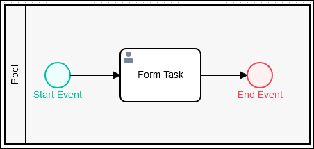
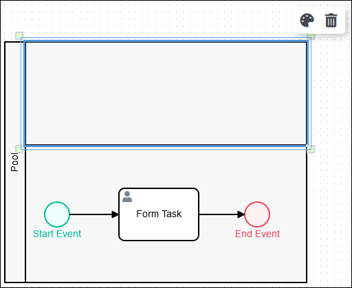
Below is a Pool object when it has been placed into a Process model. "New Pool" is the name of the Pool object.

Permissions
Your user account or group membership must have the following permissions to configure a Pool or Lane object in the Process model unless your user account has the Make this user a Super Admin setting selected:
Processes: Edit Processes
Processes: View Processes
See the Process permissions or ask your Administrator for assistance.
Add a Pool object from one of the following locations in Process Modeler:
Object Panel: Located to the left of the Process Modeler, the Object Panel contains various process modeling objects.
Object Bar: Located at the bottom of the Process Modeler, the Object Bar contains pinned Process modeling objects for quick access.
Follow these steps to add a Pool from the Object panel to the Process model:
Ensure that the Object panel is visible. If not, click the Add icon
 from the Object bar at the bottom.
Click the Pool object
 from the Object panel to select it.
Click the location in the Process model to place this object. If your process has other non-Pool objects, the Pool automatically places these objects into the new Pool when it displays.
Follow these steps to add a Pool from the Object bar to the Process model:
Ensure that the Pool object
 is pinned to the Object bar. If not, see instructions to pin it.
In the Object bar at the bottom center, click the object's icon.
Click the location in the Process model to place this object. If your process has other non-Pool objects, the Pool automatically places these objects into the new Pool when it displays.
Objects Placed Into a Pool Object Cannot Be Moved Out of It
If a non-Pool object is placed into a Pool object, that object cannot be moved outside of the Pool object. If you attempt to do so, Process Modeler places that object inside the Pool object closest to where you attempt to move it.
Deleting a Pool Object Also Deletes All Objects Within It
When a Pool object is deleted, all objects within it are also deleted. If you want to keep the objects within a Pool object, you must add those objects outside of the Pool object prior to deleting the Pool object.
If you accidentally delete a Pool object with other objects you want to keep, then click the Undo button.
Resize a Pool Object
Follow these steps to resize a Pool object:
Select the Pool object from the Process model to resize. Anchors display on each corner of the Pool object.
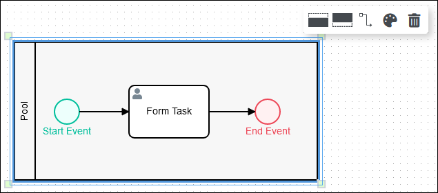
Click one of the anchors on the Pool object
 , hold your cursor, and then adjust the size of the Pool object on the Process model canvas. If the Pool object contains objects within it prior to resizing, the Pool object only resizes to contain all objects within it. Lane objects automatically adjust to the width of the Pool object, though Lane objects can be resized separately.
Pool Object Settings
The Pool object has the following panels that contain settings:
Configuration panel
Documentation panel
Advanced panel
Configuration Panel Settings
Edit the Object Name
An object name is a human-readable reference for a Process object. Process Modeler automatically assigns the name of a Process object with its object type. However, an object's name can be changed.
Follow these steps to edit the name for a Pool object:
Select the Pool object from the Process model in which to edit its name.
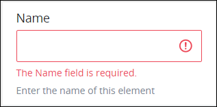
Ensure that the Configuration panel displays. If not, show it. The Name setting displays. This is a required setting.
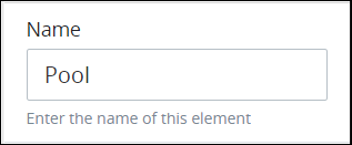
In the Name setting, edit the selected object's name and then press Enter.
Documentation Panel Settings
Describe the object's purpose and how it functions in the Process. This description does not affect Requests for the Process, but may be useful for Process model maintenance such as how the object is configured. Edit information by using the What-You-See-Is-What-You-Get (WYSIWYG) rich text editor.
A Process's entered documentation displays by selecting the View Documentation icon for that Process.
Edit the Object's Description Displayed in Process Documentation
Follow these steps to edit the description for an object:
Select the object from the Process model in which to edit its description.
Ensure that the Configuration panel displays. If not, show it. Panels to configure this object display.
Expand the Documentation panel if it is not presently expanded. The Description setting displays.
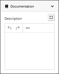
In the Description setting, edit the information to display when viewing documentation for this object and then press Enter. Alternatively, use the What-You-See-Is-What-You-Get (WYSIWYG) rich text editor to stylize your text by clicking the More icon
 .
.
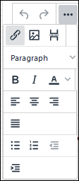
Follow these guidelines to use the WYSIWYG rich text editor to stylize your text:
Undo changes: Click on the
 icon to undo the last action.
Redo changes: Click on the
 icon to redo the last undone action.
Insert/Edit Link: Click on the
 icon to convert the selected text into a hyperlink. Follow these steps to create a hyperlink:
 Select the required text from the Rich Text control.
Click on the
icon. The Insert/Edit Link screen displays.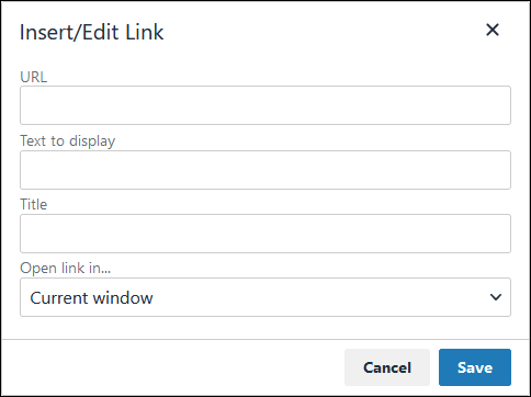
In the URL setting, enter the destination URL.
In the Text to display setting, edit or enter the text displayed in the Rich Text control.
In the Title setting, enter the text to display when a user hovers over the displayed text.
From Open link in… drop-down menu, select one of these options:
New window: Select this option to open the destination page in a new browser window.
Current window: Select this option to open the destination page in the current browser window.
Insert/Edit Image: Click on the Insert/Edit Image icon
 to insert an image. Follow these guidelines:
 Click on the Insert/Edit Image icon
. The Insert/Edit Image screen displays:
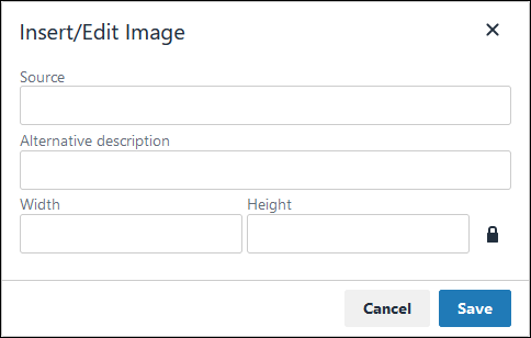
In the Source setting, enter a URL for the image.
In the Alternative Description setting, enter the text to display if the source URL of the image is not accessible.
In the Width setting, enter the maximum width for the image.
In the Height setting, enter the maximum height for the image.
Toggle the Constrain Proportions icon
 to maintain the width-height ratio of the image to its original proportion.
 Click Save.
Insert Page Break for PDF: Click on the Insert Page Break for PDF icon
 to insert a page break when a PDF document is created for this documentation if your browser supports this feature.
 Format text: Follow these guidelines to format text:
Headings: From the Paragraph/Formats menu, select Headings and then select a heading size.
Bold: Do one of the following:
From the editor toolbar, select the
 icon.
icon.From the Paragraph/Formats menu, select Inline and then Bold.
Italics: Do one of the following:
From the editor toolbar, select the
 icon.
icon.From the Paragraph/Formats menu, select Inline and then Italic.
Underline: From the Paragraph/Formats menu, select Inline and then Underline.
Strikethrough: From the Paragraph/Formats menu, select Inline and then Strikethrough.
Superscript: From the Paragraph/ Formats menu, select Inline and then Superscript.
Subscript: From the Paragraph/Formats menu, select Inline and then Subscript.
Code: From the Paragraph/Formats menu, select Inline and then Code.
Paragraph: From the Paragraph/Formats menu, select Blocks and then Paragraph.
Blockquote: From the Paragraph/Formats menu, select Blocks and then Blockquote.
Division: From the Paragraph/Formats menu, select Blocks and then Div.
Preformatted: From the Paragraph/Formats menu, select Blocks and then Pre.
Change text color: Use the Text Color drop-down to change text color. Click on the
 icon. The color palette displays. Do one of the following:
Select one of the color swatches from the color palette. The selected text changes to that color.
Click the
 icon to select a custom color from the Color Picker.
Click the
 icon to reset the text to its default color.
Align text: Follow these guidelines to align text:
Left align: Do one of the following:
From the editor toolbar, use the
 icon to left-align text.
From the Paragraph/Formats menu, select Align and then Left.
Center align: Do one of the following:
From the editor toolbar, use the
 icon to center-align text.
From the Paragraph/Formats menu, select Align and then Center.
Right align: Do one of the following:
From the editor toolbar, use the
 icon to right-align text.
From the Paragraph/Formats menu, select Align and then Right.
Justify: Do one of the following:
From the editor toolbar, use the
 icon to justify text.
 From the Paragraph/Formats menu, select Align and then Justify.
Insert a bullet list: Use the
 icon to format text as a bulleted list.
Insert a numbered list: Use the
 icon to format text as a numbered list.
Indent text: Click on the
 icon to increase text indenting.
Outdent text: Click on the
 icon to decrease text indenting.
Advanced Panel Settings
Edit the Node's Identifier Value
Process Modeler automatically assigns a unique value to each Process node added to a Process model. However, a node's identifier value can be changed if it is unique to all other nodes in the Process model, including the Process model's identifier value.
All identifier values for all nodes in the Process model must be unique.
Follow these steps to edit the identifier value for a Pool object:
Select the Pool object from the Process model in which to edit its identifier value.
Ensure that the Configuration panel displays. If not, show it. Panels to configure this object display.
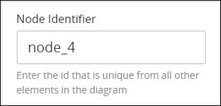
Expand the Advanced panel if it is not presently expanded. The Node Identifier setting displays. This is a required setting.
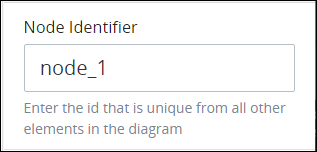
In the Node Identifier setting, edit the Pool object's identifier to a unique value from all nodes in the Process model and then press Enter.
Add a Lane to a Pool Object
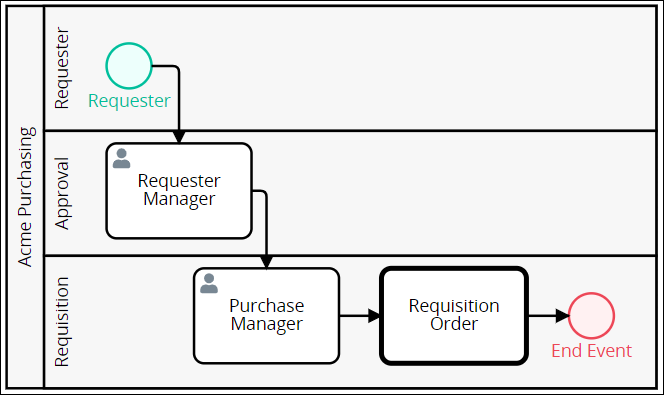
A Lane object represents a partition within a Pool object. Each Lane object indicates a role, actor, or participant within the Pool object. Text within the Lane object indicates the participant in the Process model. Any objects within the Lane object indicate that the participant is the actor or is responsible for performing actions in the Process model. Furthermore, Sequence Flow objects between objects in other Pool or Lane objects indicate with which other Process participants that Lane object interacts.
Below is a Pool object that contains three Lane objects when it has been placed into a Process model: "Requester," "Approval," and "Requisition" from top to bottom in the Pool object. Each Lane object indicates roles within the overall Process.
Permissions
Processes: Edit Processes
Processes: View Processes
See the Process permissions or ask your Administrator for assistance.
Your user account or group membership must have the following permissions to configure a Pool or Lane object in the Process model unless your user account has the Make this user a Super Admin setting selected:
Processes: Edit Processes
Processes: View Processes
See the Process permissions or ask your Administrator for assistance.
Follow these steps to add a Lane object to a Pool object:
Click the Pool object from the Process model into which to add a Lane object. Icons to add a Lane to a Pool object display.
Do one of the following:
Add a Lane object above existing Lane objects: Click the Lane Above icon
 to add a Lane object above all existing Lane objects. If only the Pool object exists, two Lane objects display.
Add a Lane object below existing Lane objects: Click the Lane Below icon
 to add a Lane object below all existing Lane objects. If only the Pool object exists, two Lane objects display.
Resize a Lane Object
Follow these steps to resize a Lane object:
Add a Lane object to a Pool object.
Select the Lane object from the Pool object to resize. Anchors display on each corner of the Lane object
.
Click one of the anchors on the Lane object, hold your cursor, and then adjust the size of the Lane object in the Pool object. If the Lane object contains objects within it prior to resizing, the Lane object only resizes to contain all objects within it. The Pool object automatically adjusts to the width of the resized Lane object so far as all objects contained within the Pool object remain contained in it. Pool objects can be resized separately.
Lane Object Settings
The Lane object has the following panels that contain settings:
Configuration panel
Documentation panel
Advanced panel
Configuration Panel Settings
Edit the Object Name
An object name is a human-readable reference for a Process object.
Follow these steps to enter or edit the name for a Lane object:
Select the Lane object from the Process model in which to edit its name.
Ensure that the Configuration panel displays. If not, show it. The Name setting displays. This is a required setting.
In the Name setting, enter or edit the selected object's name and then press Enter.
Documentation Panel Settings
Describe the object's purpose and how it functions in the Process. This description does not affect Requests for the Process, but may be useful for Process model maintenance such as how the object is configured. Edit information by using the What-You-See-Is-What-You-Get (WYSIWYG) rich text editor.
A Process's entered documentation displays by selecting the View Documentation icon for that Process.
Edit the Object's Description Displayed in Process Documentation
Follow these steps to edit the description for an object:
Select the object from the Process model in which to edit its description.
Ensure that the Configuration panel displays. If not, show it. The Description setting displays.
In the Description setting, edit the information to display when viewing documentation for this object and then press Enter. Alternatively, use the What-You-See-Is-What-You-Get (WYSIWYG) rich text editor to stylize your text by clicking the More icon
.
Follow these guidelines to use the WYSIWYG rich text editor to stylize your text:
Undo changes: Click on the
icon to undo the last action.Redo changes: Click on the
icon to redo the last undone action.Insert/Edit Link: Click on the
icon to convert the selected text into a hyperlink. Follow these steps to create a hyperlink: Select the required text from the Rich Text control.
Click on the
icon. The Insert/Edit Link screen displays.
In the URL setting, enter the destination URL.
In the Text to display setting, edit or enter the text displayed in the Rich Text control.
In the Title setting, enter the text to display when a user hovers over the displayed text.
From Open link in… drop-down menu, select one of these options:
New window: Select this option to open the destination page in a new browser window.
Current window: Select this option to open the destination page in the current browser window.
Insert/Edit Image: Click on the Insert/Edit Image icon
to insert an image. Follow these guidelines: Click on the Insert/Edit Image icon
. The Insert/Edit Image screen displays:
In the Source setting, enter a URL for the image.
In the Alternative Description setting, enter the text to display if the source URL of the image is not accessible.
In the Width setting, enter the maximum width for the image.
In the Height setting, enter the maximum height for the image.
Toggle the Constrain Proportions icon
to maintain the width-height ratio of the image to its original proportion. Click Save.
Insert Page Break for PDF: Click on the Insert Page Break for PDF icon
to insert a page break when a PDF document is created for this documentation if your browser supports this feature. Format text: Follow these guidelines to format text:
Headings: From the Paragraph/Formats menu, select Headings and then select a heading size.
Bold: Do one of the following:
From the editor toolbar, select the
icon.From the Paragraph/Formats menu, select Inline and then Bold.
Italics: Do one of the following:
From the editor toolbar, select the
icon.From the Paragraph/Formats menu, select Inline and then Italic.
Underline: From the Paragraph/Formats menu, select Inline and then Underline.
Strikethrough: From the Paragraph/Formats menu, select Inline and then Strikethrough.
Superscript: From the Paragraph/ Formats menu, select Inline and then Superscript.
Subscript: From the Paragraph/Formats menu, select Inline and then Subscript.
Code: From the Paragraph/Formats menu, select Inline and then Code.
Paragraph: From the Paragraph/Formats menu, select Blocks and then Paragraph.
Blockquote: From the Paragraph/Formats menu, select Blocks and then Blockquote.
Division: From the Paragraph/Formats menu, select Blocks and then Div.
Preformatted: From the Paragraph/Formats menu, select Blocks and then Pre.
Change text color: Use the Text Color drop-down to change text color. Click on the
icon. The color palette displays. Do one of the following:Select one of the color swatches from the color palette. The selected text changes to that color.
Click the
icon to select a custom color from the Color Picker.Click the
icon to reset the text to its default color.
Align text: Follow these guidelines to align text:
Left align: Do one of the following:
From the editor toolbar, use the
icon to left-align text.From the Paragraph/Formats menu, select Align and then Left.
Center align: Do one of the following:
From the editor toolbar, use the
icon to center-align text.From the Paragraph/Formats menu, select Align and then Center.
Right align: Do one of the following:
From the editor toolbar, use the
icon to right-align text.From the Paragraph/Formats menu, select Align and then Right.
Justify: Do one of the following:
From the editor toolbar, use the
icon to justify text. From the Paragraph/Formats menu, select Align and then Justify.
Insert a bullet list: Use the
icon to format text as a bulleted list.Insert a numbered list: Use the
icon to format text as a numbered list.Indent text: Click on the
icon to increase text indenting.Outdent text: Click on the
icon to decrease text indenting.
Advanced Panel Settings
Edit the Node's Identifier Value
Process Modeler automatically assigns a unique value to each Process node added to a Process model. However, a node's identifier value can be changed if it is unique.
All identifier values for all nodes in the Process model must be unique.
Follow these steps to edit the identifier value for a Lane object:
Select the Lane object from the Process model in which to edit its identifier value.
Ensure that the Configuration panel displays. If not, show it. Panels to configure this object display.
Expand the Advanced panel if it is not presently expanded. The Node Identifier setting displays. This is a required setting.
In the Node Identifier setting, edit the Lane object's identifier to a unique value from all nodes in the Process model and then press Enter.