An Inclusive Gateway object functions in two different ways, but not at the same time from the same object:
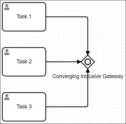
Converging workflow (synchronize workflow): An Inclusive Gateway object may synchronize Request workflow from two or more incoming Sequence Flow objects to the Inclusive Gateway object. All incoming Sequence Flow objects converging to the Inclusive Gateway object must trigger before the Inclusive Gateway object triggers, thereby synchronizing a Request's workflow. Use this coordinate workflow.

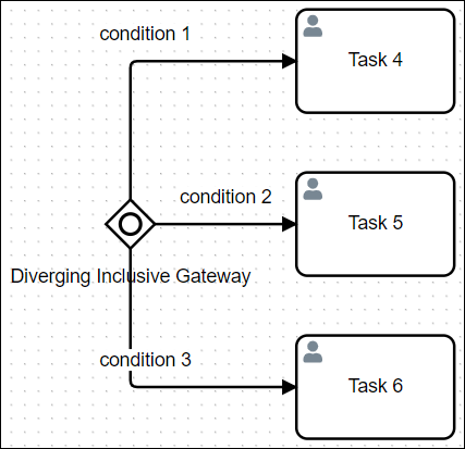
Diverging workflow (evaluate routing conditions): An Inclusive Gateway object may also evaluate a Request's workflow routing conditions for a Process. These routing conditions are configured on each outgoing Sequence Flow object from the Inclusive Gateway object. When a Request is in progress and the Inclusive Gateway object triggers, each of its outgoing Sequence Flow objects' conditions are evaluated to determine which Sequence Flow object(s) continue routing for that Request. Unlike the Exclusive Gateway object, multiple Sequence Flow objects can trigger from the Inclusive Gateway object, thereby causing multiple workflow routes simultaneously for the same Request that stem from that Inclusive Gateway object. Use an Inclusive Gateway object when you potentially want multiple workflow routes to occur simultaneously in that Request. Otherwise, consider using an Exclusive Gateway object to allow only one Sequence Flow object's condition(s) to continue workflow route for that Request.

One Inclusive Gateway object can only converge or diverge workflow, but not both. Use two Inclusive Gateway objects to both converge and diverge workflow.

Add an Inclusive Gateway to the Process Model
Permissions
Processes: Edit Processes
Processes: View Processes
See the Process permissions or ask your Administrator for assistance.
Your user account or group membership must have the following permissions to configure an Inclusive Gateway object in the Process model unless your user account has the Make this user a Super Admin setting selected:
Processes: Edit Processes
Processes: View Processes
See the Process permissions or ask your Administrator for assistance.
Add an Inclusive Gateway object from one of the following locations in Process Modeler:
Object Panel: Located to the left of the Process Modeler, the Object Panel contains various process modeling objects.
Object Bar: Located at the bottom of the Process Modeler, the Object Bar contains pinned Process modeling objects for quick access.
Follow these steps to add an Inclusive Gateway from the Object panel to the Process model:
Ensure that the Object panel is visible. If not, click the Add icon
 from the Object bar at the bottom.
Click the Gateway object
 from the Object panel to select it.
Click the location in the Process model to place this object. If your process has a Pool object, the object cannot be placed outside of the Pool.
Click the Objects drop-down menu, and then select the Inclusive Gateway option.
The Inclusive Gateway object displays.

Follow these steps to add an Inclusive Gateway object from the Object bar to the Process model:
Ensure that the Gateway object is pinned to the Object bar. If not, see instructions to pin it.
In the Object bar at the bottom center, click the object's icon.
Click the location in the Process model to place this object. If your process has a Pool object, the object cannot be placed outside of the Pool.
Click the Objects drop-down menu, and then select the Inclusive Gateway option.
The Inclusive Gateway object displays.
Replace an Inclusive Gateway Object with a Different Gateway Object
After an Inclusive Gateway object is added to a Process model, you may replace it with a different Gateway type object:
Exclusive Gateway object
Parallel Gateway object
Event-Based Gateway object
The selected Inclusive Gateway object is replaced by the default settings and color of the replacing object.
Follow these steps to replace an Inclusive Gateway object with a different Gateway type object:
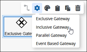
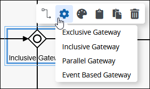
Select the Inclusive Gateway object to change to another object. Available options display above the selected object.
Click the Objects icon. The Objects drop-down menu displays the Gateway type objects. Note that the Event-Based Gateway object is only available when the Inclusive Gateway object's outgoing Sequence Flow objects connect with Catch-type Events, such as the Intermediate Signal Catch Event object or the Intermediate Message Catch Event object.
Select the object to replace the Inclusive Gateway object. The Change Type screen displays to confirm replacing the currently selected object.
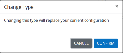
Click Confirm. The new object replaces the Inclusive Gateway object with its default settings and color.
Settings
The Inclusive Gateway object has the following panels that contain settings:
Configuration panel
Documentation panel
Advanced panel
Configuration Panel Settings
The Inclusive Gateway object has the following settings in the Properties panel:
Edit the Object Name
An object name is a human-readable reference for a Process object. Process Modeler automatically assigns the name of a Process object with its object type. However, an object's name can be changed.
Follow these steps to edit the name for an Inclusive Gateway object:
Select the Inclusive Gateway object from the Process model in which to edit its name.
Ensure that the Configuration panel displays. If not, show it. The Name setting displays. This is a required setting.

In the Name setting, edit the selected object's name and then press Enter.
Indicate Workflow Direction
Indicate if the workflow direction for the Inclusive Gateway is converging or diverging:
Converging workflow (synchronize workflow): An Inclusive Gateway object may synchronize Request workflow from two or more incoming Sequence Flow objects to the Inclusive Gateway object. All incoming Sequence Flow objects converging to the Inclusive Gateway object must trigger before the Inclusive Gateway object triggers, thereby synchronizing a Request's workflow. Use this coordinate workflow.
Diverging workflow (evaluate routing conditions): An Inclusive Gateway object may also evaluate a Request's workflow routing conditions for a Process. These routing conditions are configured on each outgoing Sequence Flow object from the Inclusive Gateway object. When a Request is in progress and the Inclusive Gateway object triggers, each of its outgoing Sequence Flow objects' conditions are evaluated to determine which Sequence Flow object(s) continue routing for that Request. Unlike the Exclusive Gateway object, multiple Sequence Flow objects can trigger from the Inclusive Gateway object, thereby causing multiple workflow routes simultaneously for the same Request that stem from that Inclusive Gateway object. Use an Inclusive Gateway object when you potentially want multiple workflow routes to occur simultaneously in that Request. Otherwise, consider using an Exclusive Gateway object to allow only one Sequence Flow object's condition(s) to continue workflow route for that Request.
One Inclusive Gateway object can only converge or diverge workflow, but not both. Use two Inclusive Gateway objects to both converge and diverge workflow.
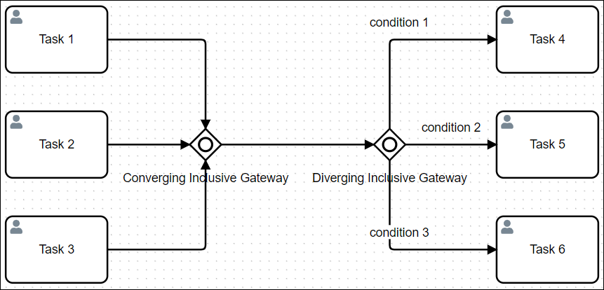
Use two Inclusive Gateway objects for both converging and diverging workflow
Follow these steps to indicate the workflow direction for an Inclusive Gateway object:
Select the Inclusive Gateway object from the Process model in which indicate the workflow direction.
Ensure that the Configuration panel displays. If not, show it. Panels to configure this object display.
Expand the Configuration panel if it is not presently expanded, and then locate the Direction setting.
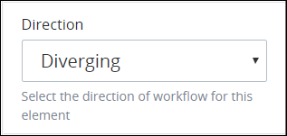
From the Direction drop-down menu, select from one of the following options:
Diverging: Select the Diverging option to indicate that the workflow direction is for outgoing Sequence Flow objects. When this option is selected, all outgoing Sequence Flow objects are evaluated to determine which trigger based on their specified condition(s). Multiple Sequence Flow objects may be triggered. This is the default option.
Converging: Select the Converging option to indicate the workflow direction is for incoming Sequence Flow objects. All incoming Sequence Flow objects to the Inclusive Gateway object must trigger before the Inclusive Gateway object triggers.
Documentation Panel Settings
Describe the object's purpose and how it functions in the Process. This description does not affect Requests for the Process, but may be useful for Process model maintenance such as how the object is configured. Edit information by using the What-You-See-Is-What-You-Get (WYSIWYG) rich text editor.
A Process's entered documentation displays by selecting the View Documentation icon for that Process.
Edit the Object's Description Displayed in Process Documentation
Follow these steps to edit the description for an object:
Select the object from the Process model in which to edit its description.
Ensure that the Configuration panel displays. If not, show it. Panels to configure this object display.
Expand the Documentation panel if it is not presently expanded. The Description setting displays.
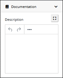
In the Description setting, edit the information to display when viewing documentation for this object and then press Enter. Alternatively, use the What-You-See-Is-What-You-Get (WYSIWYG) rich text editor to stylize your text by clicking the More icon
 .
. 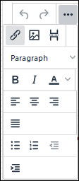
Follow these guidelines to use the WYSIWYG rich text editor to stylize your text:
Undo changes: Click on the
 icon to undo the last action.
Redo changes: Click on the
 icon to redo the last undone action.
Insert/Edit Link: Click on the
 icon to convert the selected text into a hyperlink. Follow these steps to create a hyperlink:
 Select the required text from the Rich Text control.
Click on the
icon. The Insert/Edit Link screen displays.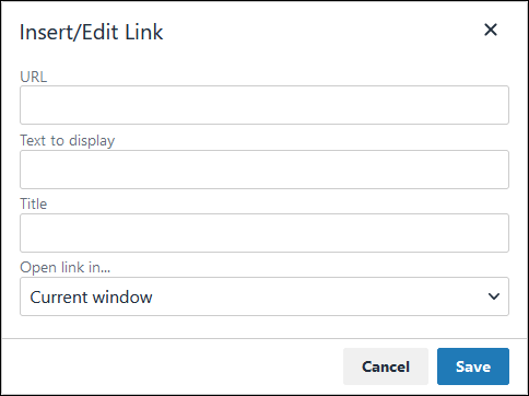
In the URL setting, enter the destination URL.
In the Text to display setting, edit or enter the text displayed in the Rich Text control.
In the Title setting, enter the text to display when a user hovers over the displayed text.
From Open link in… drop-down menu, select one of these options:
New window: Select this option to open the destination page in a new browser window.
Current window: Select this option to open the destination page in the current browser window.
Insert/Edit Image: Click on the Insert/Edit Image icon
 to insert an image. Follow these guidelines:
 Click on the Insert/Edit Image icon
. The Insert/Edit Image screen displays:
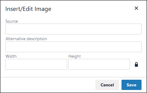
In the Source setting, enter a URL for the image.
In the Alternative Description setting, enter the text to display if the source URL of the image is not accessible.
In the Width setting, enter the maximum width for the image.
In the Height setting, enter the maximum height for the image.
Toggle the Constrain Proportions icon
 to maintain the width-height ratio of the image to its original proportion.
 Click Save.
Insert Page Break for PDF: Click on the Insert Page Break for PDF icon
 to insert a page break when a PDF document is created for this documentation if your browser supports this feature.
 Format text: Follow these guidelines to format text:
Headings: From the Paragraph/Formats menu, select Headings and then select a heading size.
Bold: Do one of the following:
From the editor toolbar, select the
 icon.
icon.From the Paragraph/Formats menu, select Inline and then Bold.
Italics: Do one of the following:
From the editor toolbar, select the
 icon.
icon.From the Paragraph/Formats menu, select Inline and then Italic.
Underline: From the Paragraph/Formats menu, select Inline and then Underline.
Strikethrough: From the Paragraph/Formats menu, select Inline and then Strikethrough.
Superscript: From the Paragraph/ Formats menu, select Inline and then Superscript.
Subscript: From the Paragraph/Formats menu, select Inline and then Subscript.
Code: From the Paragraph/Formats menu, select Inline and then Code.
Paragraph: From the Paragraph/Formats menu, select Blocks and then Paragraph.
Blockquote: From the Paragraph/Formats menu, select Blocks and then Blockquote.
Division: From the Paragraph/Formats menu, select Blocks and then Div.
Preformatted: From the Paragraph/Formats menu, select Blocks and then Pre.
Change text color: Use the Text Color drop-down to change text color. Click on the
 icon. The color palette displays. Do one of the following:
Select one of the color swatches from the color palette. The selected text changes to that color.
Click the
 icon to select a custom color from the Color Picker.
Click the
 icon to reset the text to its default color.
Align text: Follow these guidelines to align text:
Left align: Do one of the following:
From the editor toolbar, use the
 icon to left-align text.
From the Paragraph/Formats menu, select Align and then Left.
Center align: Do one of the following:
From the editor toolbar, use the
 icon to center-align text.
From the Paragraph/Formats menu, select Align and then Center.
Right align: Do one of the following:
From the editor toolbar, use the
 icon to right-align text.
From the Paragraph/Formats menu, select Align and then Right.
Justify: Do one of the following:
From the editor toolbar, use the
 icon to justify text.
 From the Paragraph/Formats menu, select Align and then Justify.
Insert a bullet list: Use the
 icon to format text as a bulleted list.
Insert a numbered list: Use the
 icon to format text as a numbered list.
Indent text: Click on the
 icon to increase text indenting.
Outdent text: Click on the
 icon to decrease text indenting.
Advanced Panel Settings
Edit the Node's Identifier Value
Process Modeler automatically assigns a unique value to each Process node added to a Process model. However, a node's identifier value can be changed if it is unique to all other nodes in the Process model, including the Process model's identifier value.
All identifier values for all nodes in the Process model must be unique.
Follow these steps to edit the identifier value for an Inclusive Gateway object:
Select the Inclusive Gateway object from the Process model in which to edit its identifier value.
Ensure that the Configuration panel displays. If not, show it. Panels to configure this object display.
Expand the Advanced panel if it is not presently expanded. The Node Identifier setting displays. This is a required setting.
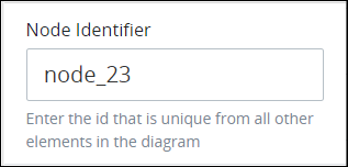
In the Node Identifier setting, edit the Inclusive Gateway object's identifier to a unique value from all nodes in the Process model and then press Enter.